This thread has been locked.

If you have a related question, please click the "Ask a related question" button in the top right corner. The newly created question will be automatically linked to this question.

XTR111: 24V issue

Part Number: XTR111

hi;

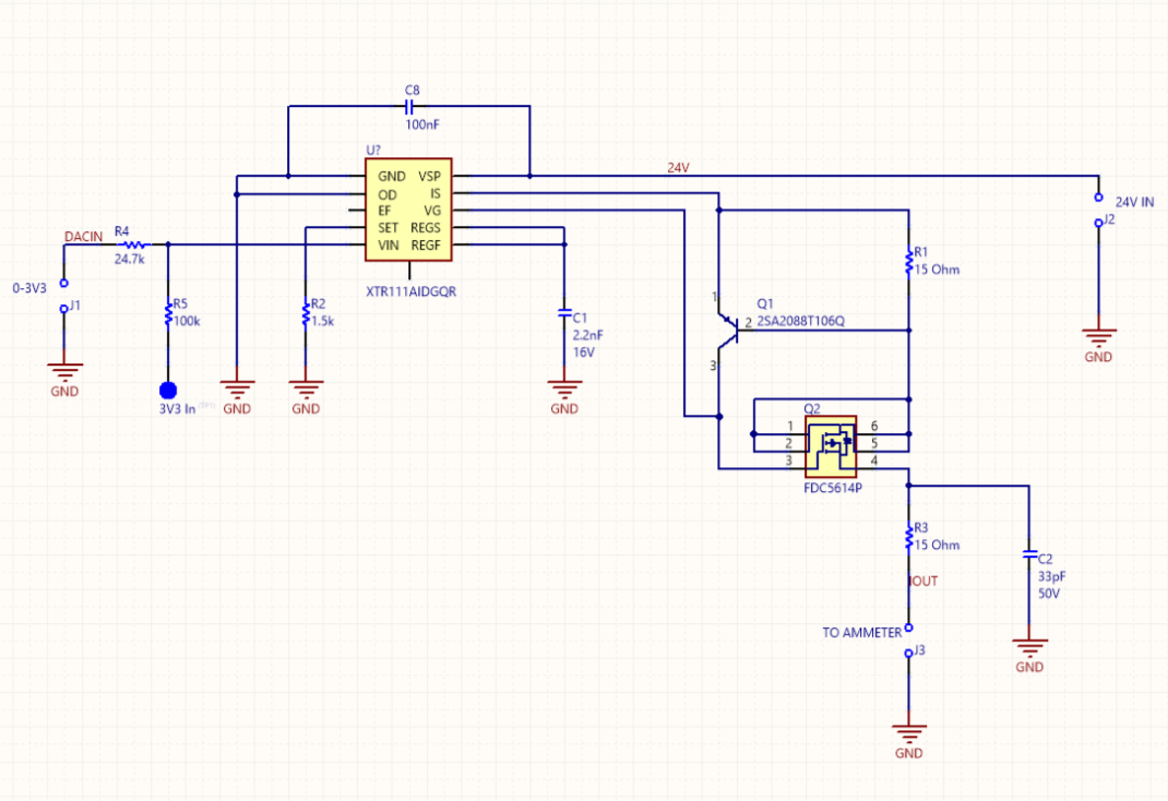
I designed xtr111 based circuit which take 0-3v3 input from dac. I want to supply with 24vdc 

In this desing when i applied 24v to xtr111 vsp pin, Output Current be around  40-44ma and unstable

if I apply 8v to VSP IOUT give me 4-20ma ouput and stable. I dont understand what is wrong ?

i didnt find same component on referance designs but i tried match features  of mosfet and bjt. 

Attached my design below.

  • Hello,

    Please understand that most of our engineers are out for the holidays. It is most likely that we won't address your question until early January 2017.
  • Hello,

    I looked through the datasheets for the BJT and MOS devices and am not immediately sure what's causing the issue. Both devices support the voltage you're trying to operate at. I have some concerns regarding the capacitance of the PMOS device used. We usually recommend devices with capacitances < 500pF. That said, the gate capacitance is higher at lower VDS voltages. Therefore, if the capacitance was an issue operating it at lower voltages would cause greater issues.

    Here are a few questions to help us with the debug process:
    1.) Have you tested multiple systems or is this occurring on only one system?
    2.) Have you properly soldered and connected the PowerPAD on the bottom of the XTR111 to your PCB?
    3.) Could you please probe the VG and Iout nodes in your system with an oscilloscope so we can observe the behavior on those pins?
  • Hi;

    Thanks for your interest. I have 2 option for mosfet but this one more close to recommended mosfets

    1- I tried 3 times but no one works well . got same problems

    2- yes i soldered it but its not professional pcb its handmade

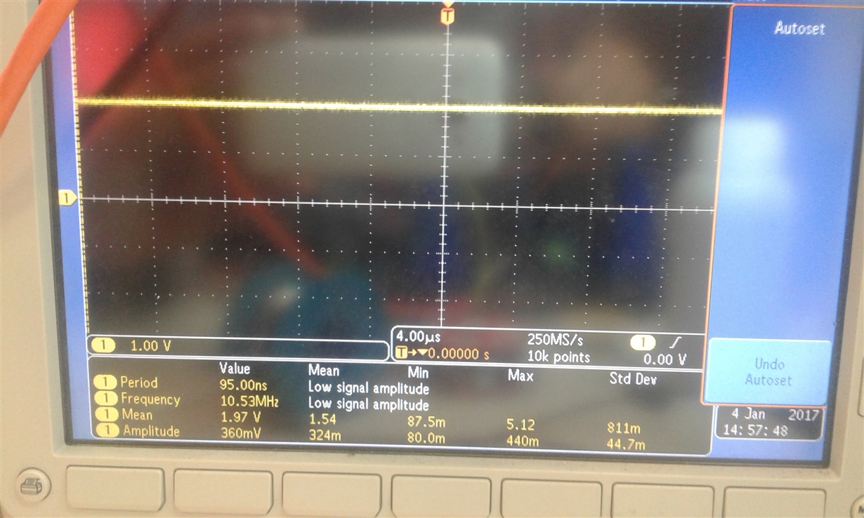
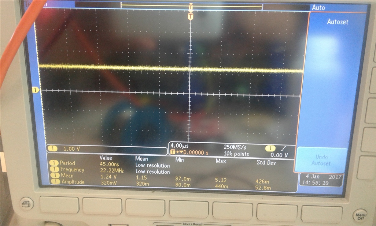
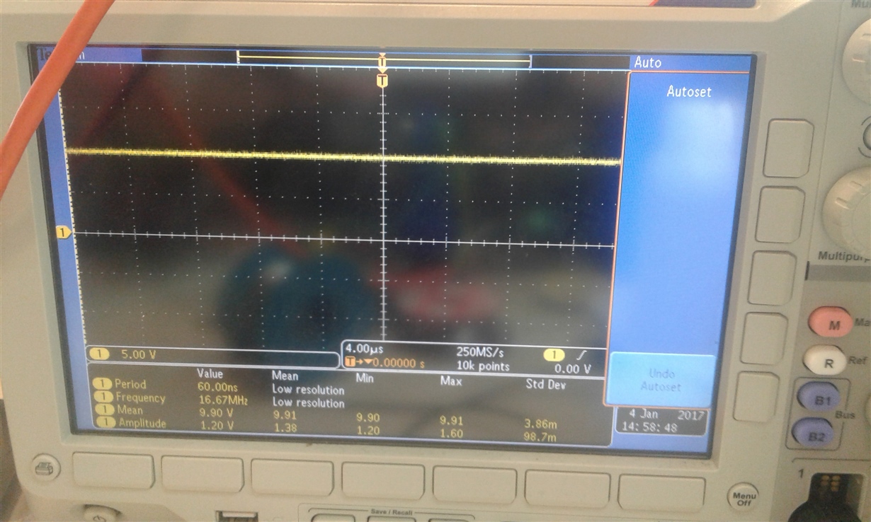
    3-i record a video about problem and i am attaching observation photos of pins you want

    explanation of video;

    •    i apply 8 volts to circuit then i change input voltage with potentiometer
    •    applied 12 volts then i change input voltage 
    •    applied 24 volts  i didnt change input voltage because 24 ma at 0 volt input

    9V VG and IOUT behaviour

    VG


    IOUT


    24V VG and IOUT behaviour


    VG


    IOUT

  • Hello,

    We're not 100% sure what's causing the issues you're experiencing but our initial guess is that this is a manufacturing issue due to the handmade PCB and loose connections around the XTR111.  We're not stating that the XTR111 is sensitive to less desirable PCB layout practices, but at the same time there are some basic PCB design and manufacturing requirements that may not be satisfied with your current PCB design.

    Furthermore, after double checking your schematic and looking at the PCB image (copied below) it does not look like you soldered the PowerPAD on the bottom of the XTR111 to the GND potential as required. In addition to requiring an electrical connection to GND, there needs to be sufficient copper area connected to the PowerPAD to properly move heat away from the XTR111. This requirement is very difficult to meet on a single-layer PCB.  We recommend that you take a look at the XTR111EVM for an example PCB layout on a 2-layer PCB. 

  • hello Collin;
    thanks for your helps. I realized that there was wrong connection of mosfet. i corrected and works well