This thread has been locked.

If you have a related question, please click the "Ask a related question" button in the top right corner. The newly created question will be automatically linked to this question.

OPA2335: Current Source circuit offset error

Part Number: OPA2335
Other Parts Discussed in Thread: LOG104, TINA-TI,

Hi,

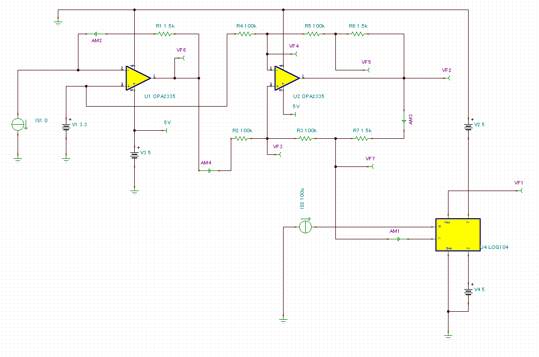
I would like to ask you a question about an offset error of "Current Source Circuit" which is shown at LOG104 datasheet page7, Figure8.

This question is related with my previous post as below.

   https://e2e.ti.com/support/amplifiers/precision_amplifiers/f/14/t/571246

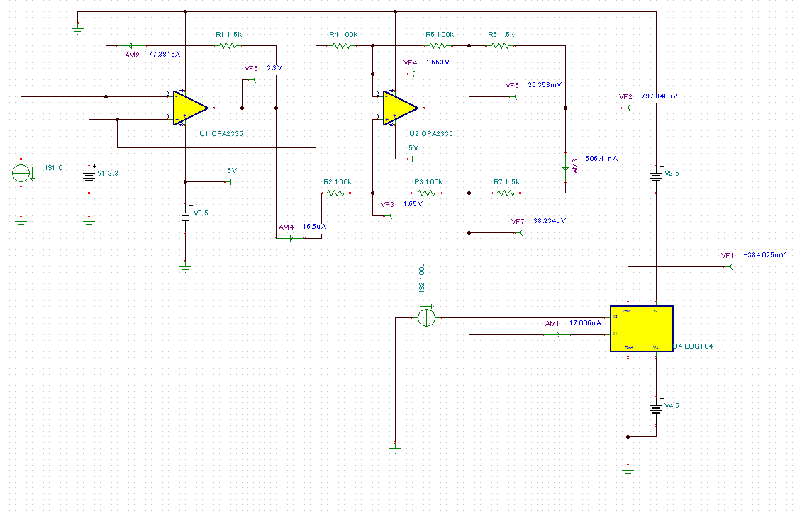
I have tried to do simulation of this circuit on TINA-TI.

And as a result, I have got an output offset error around 17uA at input current is 0A.

According to the datasheet (LOG104) Fig8, the input current range is from "10nA to 1mA" and output range is also the same as the input.

I think that the input range is limited from "17uA to 1mA" due to the offset vlaue is around 17uA.

So, could you tell me how to adjust the offset?

If I have any mistake or if you know better solution to get current source, please let me know.

Let me show my simulation circuit as below for your understanding easily.

Thank you for your support!

Best Regards,

  • Hi,

    Would you please give me any support to solve this issue?
    Thanks!
    Best Reards,
  • Suzuki-san,

    I spent a lot of time studying and simulating the input current inverter circuit shown in the LOG104 datasheet, Figure 8. I am not sure that OPA2335 V-to-I stage circuit was ever fully checked. The 17 uA minimum current results from the way the biasing conditions with 0 V applied at the input to the 100 k resistor going to the non-inverting input. The only thing that reduced the current was raising all the resistor values in the stage proportionately, but that still doesn't eliminate a minimum error current, and higher resistance resistors increase the circuit noise. Unless we can find some way to overcome that minimum current my suggestion is to not use this circuit.

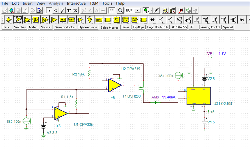
    I tried simulating the datasheet current inverter circuit in Fig. 7 and found it performed exactly as expected. You can see the TINA Spice circuit here.

    Be sure if you use this circuit that you select a MOSFET for T1 that it has a very low threshold voltage like the BSH203. You may be able to use a bipolar PNP transistor as well, but I didn't try simulating the circuit with one.

    I have attached my simulation circuit for your use.

    Regards, Thomas

    Precision Amplifiers Applicaitons Engineering

    LOG104_Cur_inv_02.TSC

  • Hi Thomas-san,

    I appreciate your great efforts to support this issue very much!!

    And I'm sorry to have kept you spending for a lot of time.

    I understood well, thanks so much!

    Best Regards,

  • Suzuki-san,

    It is my pleasure to assist you. It is helpful that you brought the issue with the Figure 8, OPA2335 current inverter to our attention.

    Regards, Thomas

    Precision Amplifiers Applications Engineering