Other Parts Discussed in Thread: MSP430F6659
Hi,
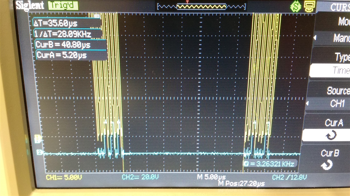
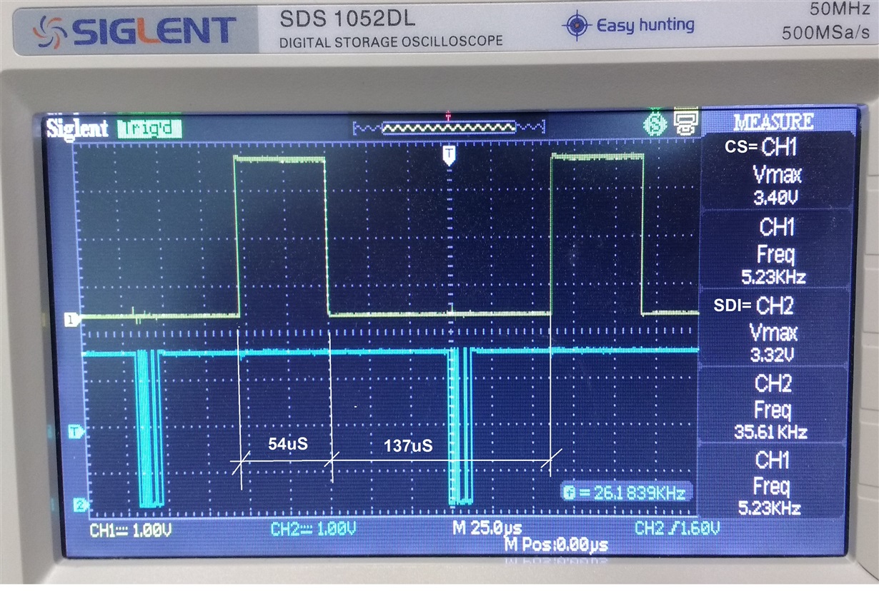
I was trying to operate PGA113 with the MSP430F6659 via SPI. First i had a delay of 35.6 uS between the first 8bit and the second 8bit, as it's shown in the next photo:
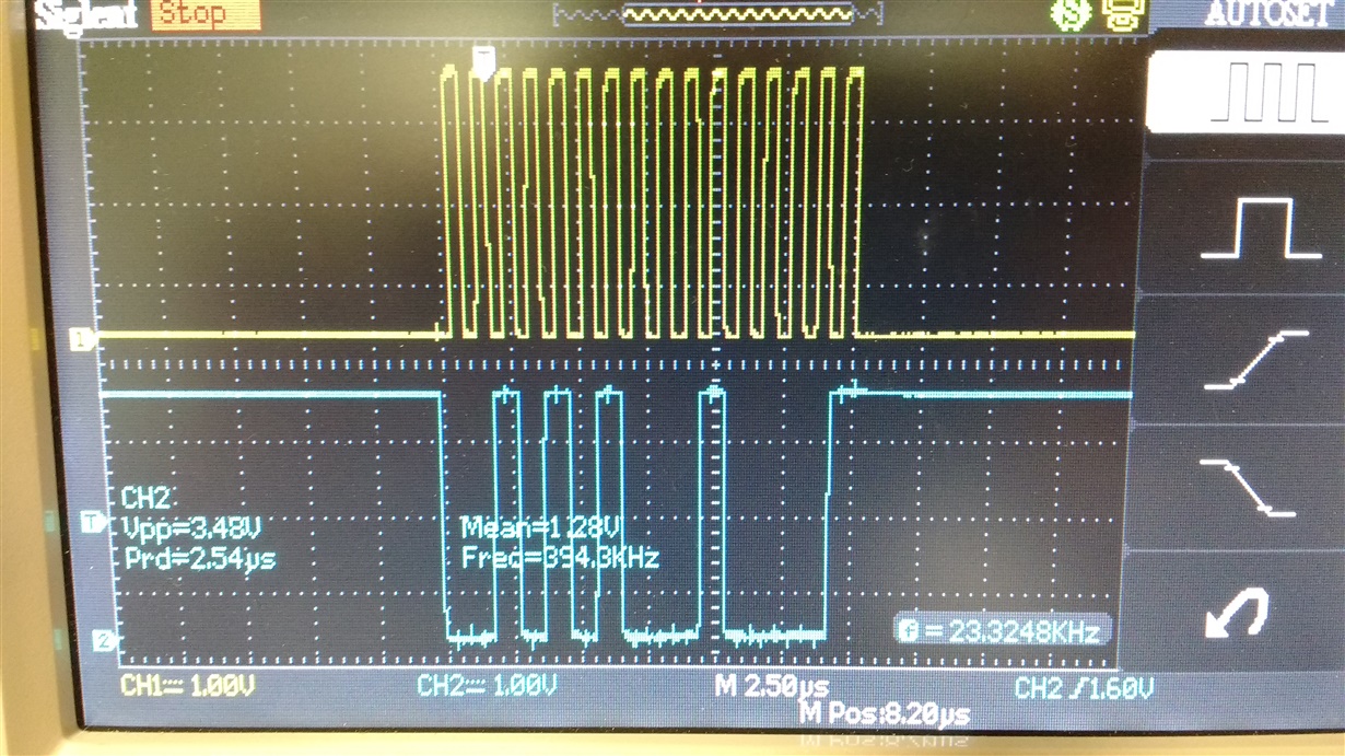
The only way I could solve this was to write the buffer a second time without asking if it is free, as seen in the ISR
UCA0TXBUF= PGA_Data1; //Escribe mas significativo
UCA0TXBUF= PGA_Data2; //Escribe menos significativo
I'm using SPI mode 10. The data that i'm sending is 0x2A21 (Gain=5 CH=1), or 0x2A20 (Gain=5 CH=0),. Vref=GND, and AVDD=DVDD=5v. The data is sent correctly in the interval in which the PGA is enabled
Without connecting the SPI pins, and with CH0/CH1 to GND, the output is 0v. When I connect a DC source to CH1 or CH0 (according to the command) and various input voltage from 0v to 0.5v the output is still 0v. These values are of the second PCB that I made with other PGA113, with the first one and the same conditions the output was 1.23v or 3v, some value of those, but it also did not change by varying the input.
I think my problem is a communication problem, but I do not see it. I also think that I respect the SPI timming
My code is:
Main.c :

//                   MSP430F6659
//                 -----------------
//             /|\|                 |
//              | |                 |
//              --|RST          P1.0|-> LED
//                |                 |
//                |             P2.4|-> Data Out (UCA0SIMO)
//                |                 |
//                |             P2.5|<- Data In (UCA0SOMI)
//                |                 |
//       PGA CS <-|P5.2         P2.3|-> Serial Clock Out (UCA0CLK)


#include <msp430.h>
#include "SPI.h"
#define  LED_DIR	P1DIR
#define  LED_OUT  	P1OUT
#define  LED		BIT0
#define  PGA_DIR    P5DIR
#define  PGA_OUT	P5OUT   //P5.2 pin 28
#define  PGA_CS	 	BIT2


unsigned int dato1=0,dato2=0,n=1;
unsigned int PGA_Data1=0x2A; //Escribir
unsigned int PGA_Data2=0x21; //Ganancia 5 CH1
//unsigned int PGA_Data2=0x20; //Ganancia 5 CH0

void main(void){

	WDTCTL = WDTPW | WDTHOLD;	// Stop watchdog timer

	Port_Mapping(); //LLamo funcion que me mapea los puertos del SPI

    Init_SPI(); //LLamo funcion que configura SPI

    PGA_DIR |= PGA_CS; //Defino como salida P3.0 que es el CS del PGA
    PGA_OUT |= PGA_CS; //Desabilito PGA
    __enable_interrupt();                     // Re-enable all interrupts

    LED_DIR |= LED;  //Define como salida el P1.0
    LED_OUT &=~ LED; //Apago el LED

while(1){


		//---------------------TX SPI PGA----------------------------------------------------------------
					__delay_cycles(50);

					PGA_OUT &=~ PGA_CS; //Habilito PGA (activo por bajo)
					__delay_cycles(50);

					n=1;
					UCA0IE |= UCTXIE ; // Habilito interrupcion transmision (al hacer esto salta a la ISR)

					__delay_cycles(50);
					LED_OUT ^= LED;
					PGA_OUT |= PGA_CS; //Deshabilito PGA
		//------------------------------------------------------------------------------------------------

		}
}


}


//-----------------------------------RUTINA DE INTERRUPCION SPI------------------------------------
#pragma vector=USCI_A0_VECTOR //vector de interrupcion, hay uno solo para transmicion y recepcion

__interrupt void USCI_A0_ISR(void)
{
switch(__even_in_range(UCA0IV,4))   //Pregunta por UCA0IV, que es registro de vectores de interrupcion
  {
	//Segun el valor de ese registro es quien genero la interrupcion

    case 0: break;                        // Vector 0 - no interrupt  //NO hay interrupcion pendiente
    case 2: break;                        // Vector 2 - RXIFG       //Se recibio un dato
    case 4:								  // Vector 4 - TXIFG     //El buffer de transmision esta libre
      switch(n){
      	  case 0:
      		  UCA0IE &=~ UCTXIE ; // Deshabilita interrupcion transmision
      		  break;
      	  case 1:
      		  UCA0TXBUF= PGA_Data1; //Escribe mas significativo
      		  UCA0TXBUF= PGA_Data2; //Escribe menos significativo
      		  UCA0IE &=~ UCTXIE ; // Deshabilita interrupcion transmision
      		  break;
      	  case 2:
      		  break;
      	  default: break;
      	 }

      default: break;
  }

}
//-------------------------------------------------------------------------------------------------

SPI.h:

#include <msp430.h>

#define SPI_MODO_00	0
#define SPI_MODO_01	1
#define SPI_MODO_10	2
#define SPI_MODO_11	3

#define MSP430_SPI_MODO SPI_MODO_10 //Cambiar aca el modo de SPI que se quiera


//************************************************************************************************************************************
// Funcion: Port_Mapping
// Configuracion el mapeo de puertos para el SPI
//************************************************************************************************************************************
void Port_Mapping(void);
//************************************************************************************************************************************

//************************************************************************************************************************************
// Funcion: Init_SPI
// Configuracion del USCI A0 SPI
//************************************************************************************************************************************
void Init_SPI(void);
//************************************************************************************************************************************


SPI.c :


#include "SPI.h"

//************************************************************************************************************************************
// Funcion: Port_Mapping
// Configuracion el mapeo de puertos para el SPI
//************************************************************************************************************************************
void Port_Mapping(void){
	__disable_interrupt(); // Disable Interrupts before altering Port Mapping registers

		PMAPKEYID  = PMAPKEY;
		//Escribir la key 2D52h me garantiza acceso de escritura a todos los registros de control de mapeo de puertos

		//Para cada port pin Px.y que tiene la funcion de mapeo, un registro PxMAPy esta disponible

	       P2MAP3 = PM_UCA0CLK; //P2.3 conecto el CLK (pin 15 bornera)
	       P2MAP4 = PM_UCA0SIMO; //P2.4 conecto el SIMO (pin 16 bornera)
	       P2MAP5 = PM_UCA0SOMI; //P2.5 conecto el SOMI (pin 17 bornera)

		PMAPKEYID = 0; //Escribiendo cualquier valor desabilito el acceso al Port Mapping


	 	P2SEL |= BIT3|BIT4|BIT5;  //Selecciono funcion periferico P2.3, P2.4 y P2.5
	 	P2DIR |= BIT3|BIT4;//|BIT5  //los defino como salida P2.3 P2.4
	 	P2DIR &=~BIT5; //defino como entrada P2.5

}
//************************************************************************************************************************************

//************************************************************************************************************************************
// Funcion: Init_SPI
// Configuracion del USCI A0 SPI
//************************************************************************************************************************************
void Init_SPI(void){

    UCA0CTL1   |=   UCSWRST;  // **Put state machine in reset**

#if (MSP430_SPI_MODO == SPI_MODO_00)
 UCA0CTL0 |= UCMST|UCSYNC|UCMSB; // 3-pin, 8-bit SPI master, MSB, Modo 0 0: Clock Fase low y Clock polarity low
#endif
#if (MSP430_SPI_MODO == SPI_MODO_01)
 UCA0CTL0 |= UCMST|UCSYNC|UCMSB|UCCKPL; // 3-pin, 8-bit SPI master, MSB, Modo 0 1: Clock Fase low y Clock polarity high
#endif
#if (MSP430_SPI_MODO == SPI_MODO_10)
 UCA0CTL0 |= UCMST|UCSYNC|UCMSB|UCCKPH; // 3-pin, 8-bit SPI master, MSB, Modo 1 0: Clock Fase high y Clock polarity low
#endif
#if (MSP430_SPI_MODO == SPI_MODO_11)
 UCA0CTL0 |= UCMST|UCSYNC|UCMSB|UCCKPH|UCCKPL; // 3-pin, 8-bit SPI master, MSB, Modo 1 1: Clock Fase high y Clock polarity high
#endif


    UCA0CTL1   |=  UCSSEL_2;   //  SMCLK (ver que el clock este bien definido)
    UCA0BR0    =  0;   // Si quisiera dividir el SMCLK cambiar aca
    UCA0BR1    =   0;  //
    UCA0MCTL   =   0;  //  No  modulation

   UCA0CTL1   &=~ UCSWRST;   //  **Initialize    USCI    state   machine**

}
//************************************************************************************************************************************


