This thread has been locked.

If you have a related question, please click the "Ask a related question" button in the top right corner. The newly created question will be automatically linked to this question.

opa381: a question about photo diode transimpedance amplifier

Part Number: OPA381
Other Parts Discussed in Thread: LMH6624

Hello, Dear TI support and all analog experts, 

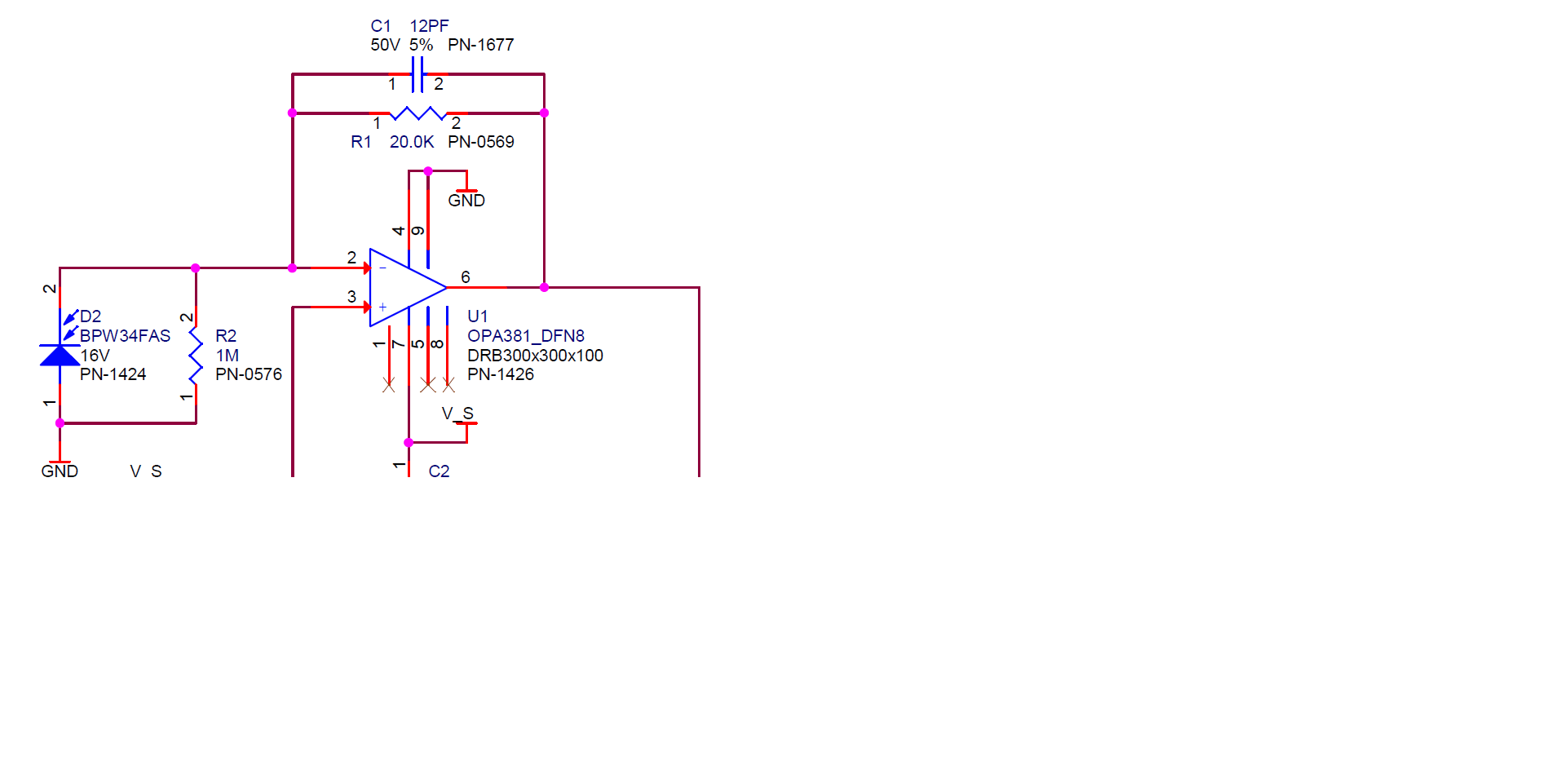
I have an old design need re-spin. I know R1 is for gain. C1 is for stability. what is the purpose of R2 in this design. couldn't find it in TI's OPA381 data sheet. 

really appreciate if anyone can explain it to me or give me a link that explain this. 

Sincerely,

David Sun

  • Hello David,

    I don't have any idea where you obtained this OPA381 transimpedance amplifier circuit so I don't know what the designer intended. The inclusion of the 1 MEG resistor across the photodiode is not something I have seen before.

    The usual way to configure a transimpedance amplifier is to simply connect the photodiode as is shown in the circuit without a resistor across it. Then, any current produced by the photodiode flows through R1 which sets the transimpedance gain (20 kV/ A). If the shunt resistor is included in the input circuit a small portion of the current generated by the photodiode will be diverted through this resistor lowering the transimpedance gain.

    Unless there is something I haven't considered, I don't believe it needs to be included in the circuit.

    Regards, Thomas

    Precision Amplifiers Applications Engineering

  • Hi Thomas
    Thank you very much for answering my question. I have another one for you, for the same design. To test the assembled board during production, easier way is to feed a 2K current source to the U1 input, by measure the output, test process will be able to tell the gain and distortion of the circuit.
    is this make sense? it is not easy to quantify the light source to generate a stable out put.
    I need a simple way to characterize this design and make a test plan. please give some suggestion. thank you for your help.

    David Sun
  • Hi David,

    The OPA381 despite being optimized for transimpedance applications can be set up as a conventional voltage feedback op amp as shown in datasheet Fig. 14. This may prove an easier way to test your boards in a production environment. The 20 k feedback resistor which is used to set the transimpedance gain in a transimpedance amplifier can serve as the feedback resistor in a conventional voltage feedback amplifier. A 2k input resistor, or whatever is appropriate to set the desired voltage gain, is added in series with the inverting input. Then, a precision reference voltage is set and applied to the 2k input resistor. 

    The inverting gain would be -20 V/V with the 20 k feedback resistor, and 2 k input resistor. If for example -100 mV is applied as the reference voltage, the output should be very close to +2 V at the output. The current through the input and feedback resistors will be 50 uA, +/- the bias current. Different input voltage levels could be used to represent different photodiode currents.

    Regards, Thomas

    Precision Amplifiers Applications Engineering

  • Hi Thomas

    I didn't make it clear enough, 2K is the bandwidth of the transimpedance amplifier. I don't know what is the easy and reliable way to characterize( quality inspection) my trans-impedance circuit board from assembly line. 

    could you please give me some suggestions?

    Appreciate your help.

    David Sun

  • Hi David,

    This is a bit outside the applications realm, but I will try to help. I suppose the production board test depends on what you have available. It would seem that if a 2 kHz bandwith with a specific transimpedance gain ( 20 kV/A) is the goal, then the test arrangement should reflect those requirements.

    Fixturing would have be developed to hold the board containing the OPA381 in a fixed position relative to the light source that stimulates the photodiode at the OPA381 input. The light source (LED) would be driven by an ac source having a frequency of 2 kHz. Taking into account the current transfer ratio of the light source and the photodiode, the light source power would have to be adjusted to produce the required diode current. The OPA381 output would be monitored to make sure that the board under test produced the needed output voltage at 2 kHz. I expect that the light source and OPA381 board would need to be enclosed in a black housing to keep extraneous light out and from affecting the photodiode input.

    Regards, Thomas

    Precision Amplifiers Applications Engineering

  • Hi Thomas,
    Thank you very much for your prompt response, that is what we are doing now. is it possible that use a current source that can generate a 2KHz AC current? for example, if we can specify an AC 20KHz 20uA Vp-p current, we feed this current the trans-impedance aplifier. should I got a 0.4V Vp_p 2KHz AC voltage.
    do you think this make sense? because it will be a little easier for me to define the input current source. otherwise I have to calibrate the optical source. which is difficult that measure the current source.

    Thanks,

    David Sun
  • Sorry Thomas,

    not AC 20KHz 20uA, it is 2KHz 20uA current source.

    thanks,

    David
  • Hi David,

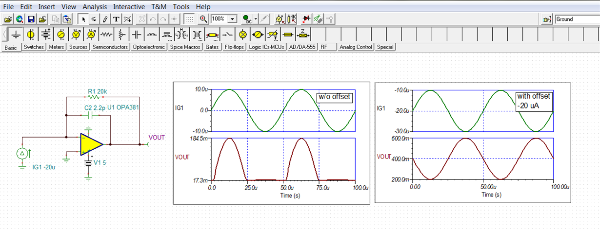
    In concept this would work, but as I recall your circuit uses a single +5 V supply to power the OPA381. A problem that would be encountered is when the +/-10 uA-pk input current swings positive, the OPA381 output voltage will try to swing below 0 V which isn't possible. That could be fixed by using a dual supply, but I think your application is already established with the +5 V supply. The net result is half the output waveform would be clipped off. This can be seen in the first plot shown below.

    A way to get around this issue and use the single supply is to introduce a current offset into the desired 20 uA pk-pk input current. For example, a -20 uA offset is added to the 20 kHz, +/-10 uA-pk input current. The result is seen the right  hand plot. The objective is to keep the output from trying to swing into the negative output rail which will be tens of millivolts, or more, above 0 volts. The actual swing level will depend on the output current to a load. In the simulation when no offset was used that appeared to be about +17.3 mV. 

    This would be a practical way to test the OPA381 transimpedance gain without involving the photodiode and light source. Keep in mind that the current through the photodiode is unidirectional and the offset isn't required as it would be with your +/- polarity signal current source. But do note that the output of the OPA381 has its limits how close it can swing to 0 V on the output. That is why the datasheet mentions adding a pulldown resistor from the output to -5 V if a true 0 V output level is required.

    Regards, Thomas

    Precision Amplifiers Applications Engineering

  • Hi David,

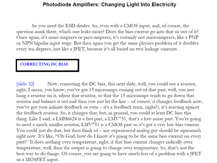
    The 1 MEG resistor is to compensate for the opamp bias current.

    Take a look at this very useful presentation:

    edge.rit.edu/.../photodiodeamplifers.pdf

    Regards,

    David.D.

  • Hi David D,

    Thanks for bringing the National presentation to our attention. I found the original script associated with the slides on line. Slide 32 explains the reasoning beind the bias current compensation for the transimpedance amplifier. It appears to be most applicable to bipolar input operational amplifiers where the input bias current is quite high as with the LMH6624. Note that the author mentions the current comes out the input

    The customer's original circuit shows a 20 k feedback, and the 1 Meg from the OPA381 inverting input to ground. I do not find any benefit to including the 1 Meg resistor to CMOS input op amps such as the OPA381, where its room temperature input bias current is typically +/-3 pA. And also as previously mentioned adding the resistor does shunt some of the photodiode current. Doing so has the effect of reducing the transimpedance gain somewhat.

    Regards, Thomas

    Precision Amplifiers Applications Engineering 

  • Hi Thomas

    Thank you very much for this detailed explanation. in the design, I will keep the package and make this 1 M ohm resistor unloaded. if everything work OK, may be next version I will remove it from the design.

    David Sun

  • Hi Thomas,

    Thanks for the explanation. 

    I find this presentation very useful, is there a chance you can share the lecture script you found?

    Thanks,

    David.D.

  • Hi David,

    I found the "Photodiode Amplifiers - Changing Light to Electricity" lecture script on line. It is listed on a web site associated with a university in Taiwan. Here's the pdf:

    Regards, Thomas

    Precision Amplifiers Applications Engineering