This thread has been locked.

If you have a related question, please click the "Ask a related question" button in the top right corner. The newly created question will be automatically linked to this question.

AMC1301: Relation between Bias Current, R4/R5 and Gain

Part Number: AMC1301

[ AMC1301 ] Relation between Bias Current, R4/R5 and Gain

Hi,

Can you help me to understand the relation between bias current and Gain?

From the drawing and description in the datasheet, I understand that the bias current can be calculated with the equation below.

Vcm = (R4 + R5 ) * Ibias

Where
Vcm = 2V
R4 = 12.5kohm
Ibias = -60uA

So R5 = 20.8kohm.

WIth these estimation, the graph can be correctly obtained. Is this understanding correct?


Here, another point, I cannot understand is the gain.
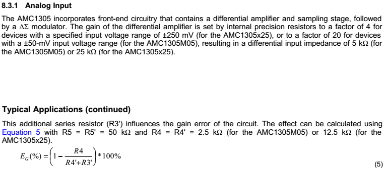
The gain of AMC1301 is fixed 8.2. I would imagine that the combination of R4 and R5 shows the indication of this gain, however not...
As far as I check the datasheet of AMC1305, it seems that there is a relation between R4/R5 and gain.
Can you help me to understand this correctly?


Thanks,
Ken


  • Hi Ken,

    You mention two different parts above - the AMC1301 (an isolation amplifier) and the AMC1305 (an isolated DS Modulator). Both devices have a similar front end circuit with gain = 4 (R4 = ~12.5k and R5 = ~50k). For the AMC1301, an additional gain factor of 2.05 is included in the back end.
  • Hi Tom,

    Thank you for sharing information!
    I see that the gain(8.2) of AMC1301 is consisting of front-end gain (4) and back-end gain (2.05).

    Can you help me to understand the bias current calculation?
    Now I know my equation above is not valid (R5 = 50kohm, not 20.8kohm).
    How can I get the bias current value?

    Thanks,
    Ken
  • Hi Ken,

    The 60uA bias current is total current for both inputs to the AMC1301.  The current is measured with inputs shorted together and then tied to GND. It is ~30uA for each pin.

  • Hi Ken,

    If you would prefer not to use the plot of bias current vs. common-mode voltage, then alternatively you could approximate the bias current as ( Vcm - 2V)/(R4+R5), where the 2V is the common-mode voltage the output of the internal amp is biased to, Vcm is the input common-mode voltage, R4 = 12.5kOhm and R5 = 50kOhm. Multiply the result by two to get the total bias current on both pins. The result is very close to what we spec, but deviates slightly, which I suspect is due to the bias current of the internal amp.

    Regards,
    Zak Kaye
    Precision Amplifiers Applications
  • Hi, Tom, Zak,

    Thank you a lot for sharing the knowledge! This is what I wanted to know!
    I will consult with my customer!

    Regards,
    Ken