This thread has been locked.

If you have a related question, please click the "Ask a related question" button in the top right corner. The newly created question will be automatically linked to this question.

INA125: Gain Variation with different instances of amplifier

Part Number: INA125

Hello all,

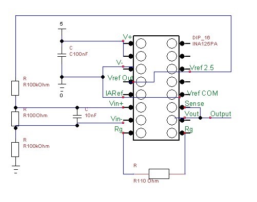
I have an issue with a ciruit that contains an INA125 amplifier. The circuit shall be used to amplify the signal of a load cell that is afterwards converted by an Analog Digital Converter.

For testing I setup some resistors instead of the load cell that should give a constant voltage that is amplified. The gain should be ~550, given an input voltage between Vin+ and Vin- of 0.00125V is should get ~0.688V at the output of the circuit.

However at the ouput I get different voltages, that are reproducible with selected instances of INA125. I have 20 INA125 here and by changing the amplifier in the circuit while keeping the rest the same I get a different output voltage.

I also tried to check for voltage offset by taking the difference of both Vin+ and Vin- connected to one side of the 100Ohm resistor and Vin+ and Vin- connected as shown below.

Do you see any error in the circuit below?

Best regards

Florian

  • Hi Florian,

    I suspect the issue you are seeing is caused by a violation of the output limitations of the device. Take a look at input common-mode voltage vs output voltage curve below. Since you are operating with a single +5V supply, your minimum output voltage looks to be around 600-700mV. Since you are expecting an output right at the edge of this limitation, it's likely that you are seeing a slight variation in this parameter where some parts are able to maintain linear operation and others are not. As a quick check you could try testing the devices with dual supplies and see if the variation goes away, or you could increase either your differential input signal or gain.

    Regards,

    Zak Kaye

    Precision Amplifiers Applications

  • Florian,

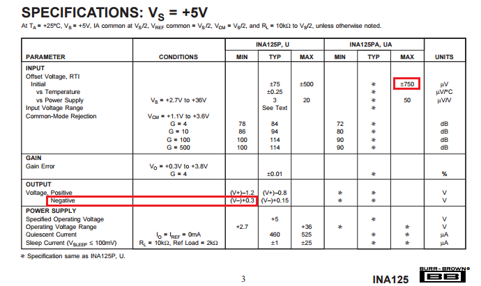
    The nominal voltage of 1.25mV you apply at the input of INA125 should result in the nominal output voltage of 688mV BUT you must also account for the significant variation in the INA125 input offset voltage which depending on the INA125 grade you use it may be as high as +/-750uV and thus significantly effect your actual measurement: 0.275V<Vout<1.1V.  Additionally, in the case of the input offset voltage being at the negative end of the specified range (-750uV), the resulting output voltage in single supply 5V application would violate the specified minimum output voltage range of 0.3V - see below.  

    All of the above considerations do not take into account additional errors caused by the resistors’ tolerances used. 

  • Hi Zak, hi Marek,

    thanks for the fast answer. I wasn't aware about operating out of the specified ranges. For the load cell application increasing the gain is not an option, as the normal state should be zero difference between V_in- and V_in+. The dual supply would help, however these would be additional parts and circuit.

    I looked through the data sheet but found no statement, how the reference voltages below the one connected to V_Ref_Out behave and what
    s the error on them. One option would be to connect IA_ref to V_ref_bg to raise the output signal by the Band Gap Voltage. The voltage does not need to be accurate but stable over some time as the load cell will be calibrated to zero load anyhow. Then I would just lower the gain to stay in the range of the ADC.

    What do you think of this option?

    Best regards
    Florian