This thread has been locked.

If you have a related question, please click the "Ask a related question" button in the top right corner. The newly created question will be automatically linked to this question.

INA126: Amplifying a very small A/C voltage

Part Number: INA126
Other Parts Discussed in Thread: TINA-TI, OPA388, INA163, OPA192, OPA2192

Hi, I'm trying to build an EMF detector which can detect very low levels of EMF.

I have a coil which outputs approx 0.2V AC when subjected to very high levels of EMF from a demagnetiser (50Hz?). But I want to amplify the coil's output so that I can easily detect very low levels of EMF with it.

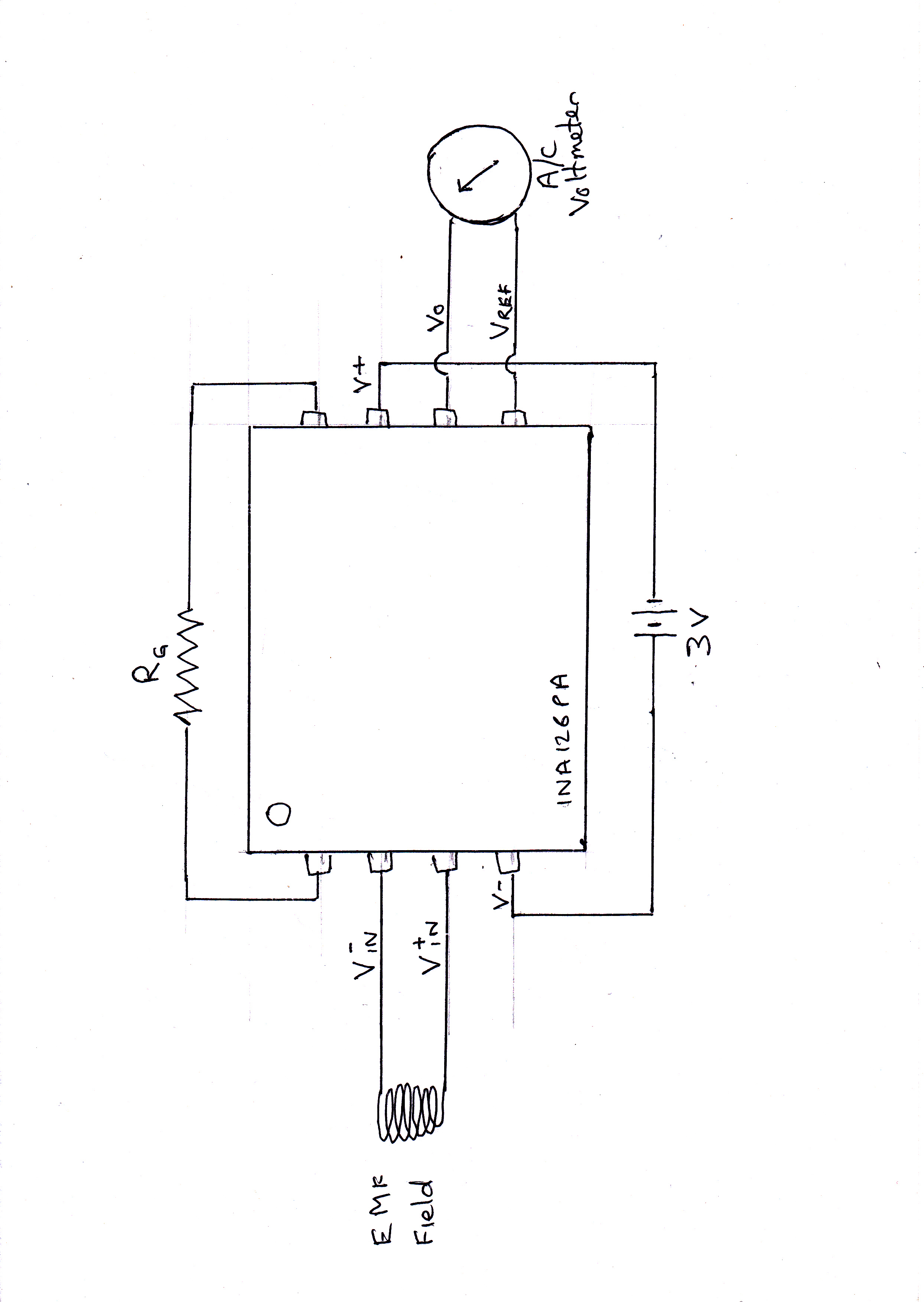
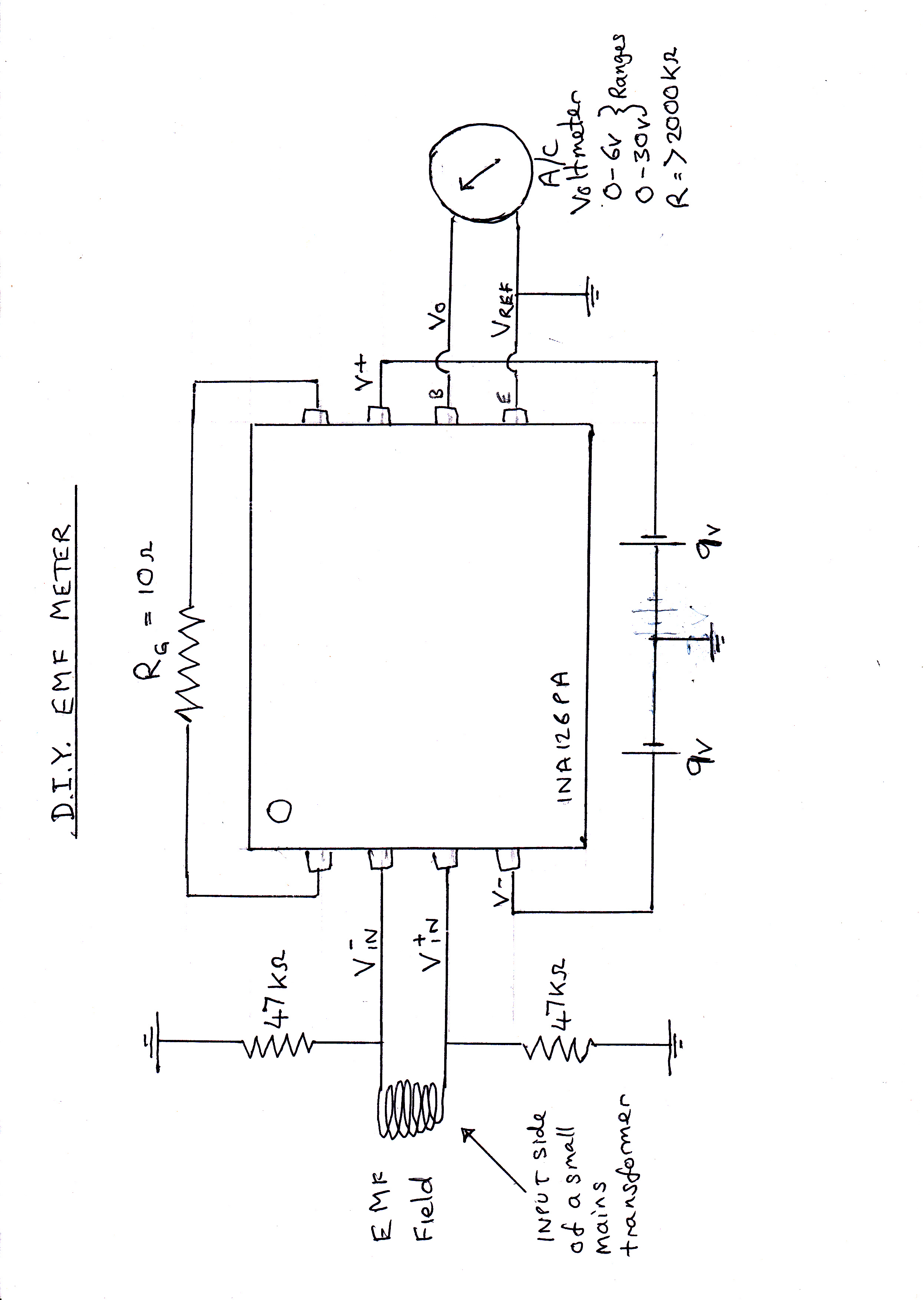
I am using an instrumentation amplification IC (INA126PA) to amplify the 0.2V AC signal and an AC voltmeter to measure the output. I want this to be about 100V AC, but at the moment I am getting OV, with or without a 100 ohm external resistor (RG)

I have included a circuit diagram below. The circuit is currently on a breadboard. My 3V supply is from 2 x 1.5V batteries.

I'm sure I have done something really silly. Can anyone please tell me (simply) what it is?

Regards,

Alan.

  • Hello Alan,

    There are a few things to consider here.

    1. Are you trying to get a 100V peak-to-peak swing or a gain of 100 Volts/Volt?

    In either case you will not be able to truly accomplish this since the max output will be your positive supply voltage (1.5V) minus roughly 0.75V depending on your load resistance. Your negative swing will also saturate at your negative supply (-1.5V) plus 0.8V. The maximum amount of power you can supply to this part is +-18V (dual supply) or 36V (single supply), thus maximum output voltage swing you can accomplish will be 36V peak-to-peak or just below a gain of 36/0.2 = 180 V/V. Overall, consider increasing your dual supply voltage to increase your possible output voltage swing.

    2. ***You need to include input bias current paths for the inputs of the IC. (This is most likely why you're not measuring any output)***

    I ran simulations in TINA-TI and these paths were needed to see a voltage output. These paths are two resistors connecting Vin+ and Vin- to ground. I chose 47kOhms as seen in section 8.2.2.3 of the INA126 datasheet, but you may want to consider other values depending on your application.

    3. You should connect your reference pin to ground and measure the voltage output from Vout to ground.

    If you operate the amp with a single suppply voltage, then you will want to connect Vref to mid-supply power rail. In this case, measuring the output from Vout to Vref will not work.
  • Thank you very much Peter. Your advice was spot on. I didn't actually need 100v output (rms), I just wanted enough to give me a good reading on my AC voltmeter. Following your advice, I used 2 x 9v supply with earth as their mid point and put the two 47kOhms resistors in you recommended. This gave me a maximim reading of 16V A/C which is quite adequate. When I then reduced Rg to 10 Ohms the sensitivity to EMF increased dramatically, and though I have yet to calibrate it, I'm sure it will now be fit for purpose. I would like to follow this email up with one with the updated circuit diagram attached so that others can use this to build their own EMF meter. Will your system allow me to do this?
  • Yes you should be allowed to attach a file or insert an image. Completely up to you.

    Peter Iliya

    Precision Applications

  • Hi Peter,

    I've tried to respond with some questions and 2 diagrams, but it won't allow me to insert them as I did in my initial post. Do you know a way round this?. If not I will start a new thread.

    Regards,

    Alan Morris
  • Use should be able to insert files/media or attachments. Did you click the "Use rich formatting" link at the bottom right of your reply screen? This brings up all of the editing features to your replies.

  • Hi Peter,

    I am now using Rich Formatting and have tried sending you the two diagrams by "Paste from Word" which worked before (ctrl C, ctrl V) and then by "Insert File" (as a jpg), but neither appear to be working. I have checked that my PC is working OK, by copying and pasting into a blank page and had no problem. Maybe I could send them attached to an email, or send them by post or start a new thread??

    Best Regards,

    Alan Morris

  • Hi,

    Please see below, my circuit diagram which is for an EMF detector employing an INA126PA instrumentation amplifier. I've tried it and it works quite well, but after some testing, I now realise that it needs to be more senistive to low A/C voltages in order to get the EMF sensitivity I need.

    Using this circuit I am getting a couple of volts A/C from a very small induced A/C input, which unfortunately I can't measure as my multimeter doesn't go down that low, but since I am using a 10 ohm resister for Rg and getting 1v A/C meter reading in my test, I must assume that the input signal is around 0.1mV. However, this equates to about 1milligauss, and I am looking for readings down to 0.01milligauss, so I really need to multiply the sensitivity by 100.

    I wondered if it is possible to get this degree of amplification using 2 x INA126PA instrumentation amps in series? Or would you recommend a different approach, e.g a different TI amplifier?

    Regards,

    Alan Morris

  • Hello Alan,

    I can see your circuit. What is your problem?

    Peter Iliya
    Precision Amplifiers
  • Hi Peter, looks like you saw my first draft of my message and not the updated version.

    My circuit diagram is for an EMF detector employing an INA126PA instrumentation amplifier. I've tried it and it works quite well, but after some testing, I now realise that it needs to be more senistive to low A/C voltages in order to get the EMF sensitivity I need.

    Using this circuit I am getting a couple of volts A/C from a very small induced A/C input, which unfortunately I can't measure as my multimeter doesn't go down that low, but since I am using a 10 ohm resister for Rg and getting 1v A/C meter reading in my test, I must assume that the input signal is around 0.1mV. However, this equates to about 1milligauss, and I am looking for readings down to 0.01milligauss, so I really need to multiply the sensitivity by 100.

    I wondered if it is possible to get this degree of amplification using 2 x INA126PA instrumentation amps in series? Or would you recommend a different approach, e.g a different TI amplifier?

    Regards,

    Alan Morris
  • With a 1V peak-peak output and gain = 5 + 80,000/10 = 8005V/V, your input differential signal must be 0.124mV pp, but you must take caution into the INA126's noise and bandwidth.

    What frequencies are you considering inducing into the coil?

    You may be able to just use the INA and another op-amp to satisfy the overal gain as well.
  • Alan,

    Another thing to consider is to AC couple your signal since you have to be careful about amplifying the input offset voltage of your INA. You can remove this DC offset by putting an integrator in the feedback into the reference pin. Although you will want the integrator's cutoff frequency (1/2piC1R1) to be less than the frequency of the coil signal you are trying to amplify. You also want this integrator amplifier to have low input bias current.

  • Hi Peter,

    I honestly have no idea what frequency will be introduced into the coil. I guess it could be anything from 50Hz upwards, including radio frequencies and mobile phones. In fact I hope to use a frequency counter in series with the output (via a very small capacitor) to find out the frequencies of signals obtained.

    If you think that coupling it with an op-amp will work, I will certainly try it. The circuit diagram you have provided in your second post looks very interesting. Am I right in thinking that Vref and Vout2 are the amplified outputs, while Vout1 and earth are the current ones? Does V29 and V19 mean 29V and 19V respectively? Only I was hoping to keep my supply voltage down to 18V (2 x 9V batteries) as it is meant to be a portable device.

    Regards,

    Alan Morris

  • In the previous circuit, Vref is the DC offset of the output from the INA. It is created by integrating the output of the INA at a frequency of 1.59 Hz and is fed into the reference pin. Effectively the gained up input voltage offset of the INA is then subtracted from the output. Vout1 is the signal after its first amplification from the INA. This is fed into the OPA388 with respect to ground and amplfied again to result in the final amplified signal Vout2. "V2 9" and "V1 9" are both 9V batteries labeled as nodes V2 and V1.

    The noise of the amps you choose will be critical, but it seems you will need some bandwidth if you plan on amplifying radio and mobile phone frequencies.

    Here is another circuit that's using the INA163, a very low noise INA that will reduce your noise by half compared to the INA126. You can run the simulation in TINA-TI and see how it can amplfy a 1uVpp/50Hz signal to a 1Vpp at Vout2.

    ina163e2e.TSC

  • Very many thanks Peter,

    I will start ordering the parts right away.

    Regards,

    Alan.

  • Hi Peter, 17.5.17

    Re. the circuit diagram you sent me on 5.5.17.

    I bought the components and assembled them on a breadboard to check performance with my AC voltmeter connected to Vout and Vref. No meter response was obtained, but the OPA388 chip got extremely hot instantly, so I had to disconnect.

    I attach the diagram you sent me with added terminal numbers for OPA192IDR and OPA388IDR, which I deduced from their technical data sheets. I had to assume that the vertical stripe in front of the lettering on the chips was the equivalent to the large dot on the INA163UA/2K5, so presumed the tag just underneath it was no.1. The other diagram I attach is of my actual wiring and so may explain the position of this stripe better.

    NB : As the amps were all Surface Mounts, I had to solder them to IC adaptors, which meant that on the breadboard, the chips are actually at 90o to the adaptors. But to avoid confusion, I have shown them as if they were the 'though hole' type.

    Could you please tell me if I have misinterpreted your diagram or incorrectly labelled the tags on the chips?

    Or could the OPA388 chip be faulty?

    Regards,

    Alan Morris

  • Hello Alan,

    The reason the OPA388 is overheating is because the supply +/-9V is above the absolute maximum rating of +/-3V or 6V single supply. I would recommend reducing the supply voltage to +/-2.5V.

    Best,

    Errol Leon
    Texas Instruments
    Precision Op Amp Applications
  • Hi Errol & Peter,

    Thanks for this information. By using the INA163 circuit Peter supplied (see previois post) and putting a 100 ohm resistor between the +9v and the OPA388, and another between the -9v and the OPA 388, I was able to reduce the voltage supply fto the OPA388 from +/-9v to +/- 1.8v.

    I know this is short of the optimum +/- 2.5v, but I still expected to see a big (100x) improvement over the amplification I got with the INA126 on its own (see below),. But instead I got much the same as before. Is this because we can't use +/- 9v source on the OPA388 as planned? In which case could it be replaced by a suitable OP amp that can take this voltage?  Or can you suggest another solution?

    I haven't yet tried the earlier design of Peter's where INA126 was used in combination with OPA192 and OPA388, but since OPA388 seems to be the source of the problem, I doubt if that would be any better. 

    Regards,

    Alan Morris

  • Alan,

    I aplogize for the confusion about supplying the OPA388 with a +-9V supply in earlier schematics, but simply connecting a 100-Ohm resistor in-series with the 9V battery and the supply rails of the party will not bring down the voltage supplied to the OPA388. It will only increase the source resistance which will affect output distortion and present possible stability issues. Maybe I am misinterpreting this. The power supplied to the OPA388 needs to be +2.5V on V+ and -2.5V on V-. You could accomplish with a resistor divider network and buffer this output into the OPA388.

    If you don't want to do this, you can use another part that can accept +-9V supply like the OPA192.
  • Hello Alan,

    To add to Peter's response you can use OPA2192 which is the dual channel of the OPA192.

    Best,

    Errol

  • Thanks to both of you,

    I had measured the potential difference between tab 4 and tab 7 and got 3.6v with the two resistors in place, then assumed this meant +/-1.8v supply to the OPA388, but I admit to not being very sure of myself in my understanding of this. It seems I have 3 options available :-

    1) build a resistor divider - but this will surely be a drain on my batteries
    2) replace the OPA388 with another OPA192
    3) replace both the OPA192 and OPA388 with an OPA2192

    Of these, no.3 sounds the simplest. Is there any chance of one of you updating my circuit diagram for this option? I can get the OPA2192 from Farnell, but I would also want to get any other resistors or capacitors at the same time.

    Sorry to take up so much of your time, but I am very keen for this to work.

    Best Regards,

    Alan Morris
  • Hi Peter,

    Just wondered if you had read my last email and will be able to supply me with an updated circuit diagram?

    No massive urgency, but would like to know if it is in the pipeline.

    Best Regards,

    Alan Morris

  • Hello Alan,

    Attached is an updated TINA TI  schematic with OPA2192.  Also make sure to have decoupling capacitors of 100nF as close to the supply pins of each device.

    Best regards,

    Errolina163e2erevb.TSC

  • Hi Errol,

    Thanks very much for supplying this circuit. I purchased an OPA2192 and tried it out with the INA163 on my breadboard - I attach your diagram with the 1-8 tags for the OPA2192 labelled on it.

    Unfortunately I got no Vout signal whatsoever, even when I exposed it to a very high EMF signal that should have resulted in maximum AC Volts response.

    So, now that I have the Tina program on my PC, I noted all the nodal DC and AC voltages from this circuit and compared them to those measured on my breadboard. I attach this table and have pasted it below. Where my readings differ significantly from those in the Tina program, I have made them bold. It seams that apart from the two supply voltages, all the others on INA163 are way off. Whereas the readings from my OPA2192 look OK (bearing in mind I can't read less than 1mV DC or 100mV  A/C), apart from the Vout2 on tab 1.

    It looks to me like the INA163 is faulty. Do you agree? Is there any way I can test to confirm? Should I buy another and try again?

    Best Regards,

    Alan Morris

    ina163e2erevb with tabs.TSC

    INA163 + OPA2192 Test Results

    Amplifier

    Node Tested

    Nodal DC voltages

    Nodal AC Voltages

    From Tina

    From breadboard

    From Tina

    (Amplitude)

    From breadboard

    INA163

    1

    95mV

    -150mV

    990uV

    2.4V !!

    2

    Not Connected

    Not Connected

    Not Connected

    Not Connected

    3

    94mV

    -600mV

    500nV

    <100mV

    4

    94mV

    -20mV

    500nV

    <100mV

    5

    94mV

    -20mV

    500nV

    <100mV

    6

    -9V

    -7V

    0V

    <100mV

    7

    Not Connected

    Not Connected

    Not Connected

    Not Connected

    8

    -9.6uV

    -60mV

    1.4mV

    <100mV

    9

    -9.6uV

    -60mV

    1.4mV

    <100mV

    10

    -33uV

    +20mV

    63uV

    <100mV

    11

    +9V

    +7.5V

    0V

    0V

    12

    94mV

    -600mV

    490nV

    <100mV

    13

    Not Connected

    Not Connected

    Not Connected

    Not Connected

    14

    95mV

    -500mV

    990uV

    <100mV

    OPA2192

    1

    3.3mV

    <1mV

    930mV

    <100mV

    2

    -2.6uV

    <1mV

    44uV

    <100mV

    3

    0V

    <1mV

    0V

    0V

    4

    -9V

    -7V

    0V

    0V

    5

    0V

    0V

    0V

    0V

    6

    -3uV

    <1mV

    63uV

    <100mV

    7

    -33uV

    <1mV

    63uV

    <100mV

    8

    +9V

    +7.5V

    0V

    0V

    INA163 + OPA2192 test results.docx

  • Hey Alan,

    I think providing some more information might be helpful such as the frequency of the EMF signal you're presenting to the coil and how you're measuring the AC values. As well as the layout of your board.

    With the current gain configuration of IN163 at Rg = 3 Ohms, it will have a BW of less than 100kHz. The last stage OPA192 will have a BW of 21kHz with its current gain of 470. Anyway, knowing what frequency you're using will help to know if this is the problem.

    Additionally, you can't directly compare the DC nodal values between simulation and your breadboard. The offsets in the system can be completely different in real life vs. what they default to in TINA. Did you take these DC measurements when exposing the coil to the EMF signal?

    Are your AC nodal values peak-to-peak, rms? Are they fluctuating? Oscilloscope screen shots would be helpful? If your INA163 pin 1 is stuck at 2.4V then that could be the root of the problem.

    Maybe debugging each amp separately and simulating coil voltage signals with a function generator to ensure everything is working by itself is your best option.

    Peter Iliya
  • Hi Peter,

    I attach my wiring diagram as requested, and I have remeasured the DC and AC voltages both with and without the EMF Signal. This table is seen below. I suggest you ingnore my earlier set of measurements as I think there were some errors in them. My EMF source, where used was within a couple of inches of the coil detector. At this distance, the earlier circuit  with INA126 would have given an AC response of more than 0.2V. 

    Unfortunately I don't have an Oscilloscope or a function generator, so I can't provide readings from these.

    The EMF signal is from a 50Hz power supply.

    Best Regards,

    Alan.

    Repeat of INA163 + OPA2192 Test Results with and without EMF signal 1.6.17

    Sorry - table has got slightly corrupted - the first 2 columns of figures should be under Nodal DC and the last 2 under Nodal AC.

    Amplifier

    Node Tested

    Nodal DC

    voltages 

    Nodal AC Voltages (rms)

    Without EMF 

    With   EMF     

    Without

    EMF

    With EMF

    INA163

    1

    0.5-1.0V

    80mV

    <100mV

    5.0V

    2

    <10mV

    <10mV

    <100mV

    <100mV

    3

    600mV

    540mV

    <100mV

    <100mV

    4

    -20mV

    -20mV

    <100mV

    <100mV

    5

    -20mV

    -20mV

    <100mV

    <100mV

    6

    -7V

    -7V

    <100mV

    <100mV

    7

    <10mV

    40mV

    <100mV

    <100mV

    8

    100mV

    40mV

    <100mV

    5.0 to 6.0V

    9

    100mV

    40mV

    <100mV

    5.0 to 6.0V

    10

    600mV

    0.8-1.4V

    <100mV

    <100mV

    11

    7.5V

    7.5V

    <100mV

    <100mV

    12

    -600mV

    -600mV

    <100mV

    <100mV

    13

    <10mV

    <10mV

    <100mV

    <100mV

    14

    <10mV

    <10mV

    <100mV

    5.0 to 6.0V

    OPA2192

    1

    <10mV

    <10mV

    <100mV

    <100mV

    2

    <10mV

    <10mV

    <100mV

    <100mV

    3

    <10mV

    <10mV

    <100mV

    <100mV

    4

    <10mV

    <10mV

    <100mV

    <100mV

    5

    <10mV

    <10mV

    <100mV

    <100mV

    6

    <10mV

    <10mV

    <100mV

    <100mV

    7

    <10mV

    <10mV

    <100mV

    <100mV

    8

    7.5V

    7.5V

    <100mV

    <100mV

  • Hi Peter,

    I just wondered how you are getting on with solving this riddle. While I was waiting, I tried three things out :-

    1) Going back to using INA126 on its own

    2) Connecting OPA2192 to INA126

    3) Trying INA163 on its own

    Here's what I found ;-

    1) With INA126 on its own (Rg = 3 ohms) I get an output of 1.7V A/C with source at 44cm, and a max of 5.8v with source at 20cm.

    2) Adding OPA2192 to INA126 had a detrimental effect, making the zero (source removed) 5.5v A/C, and reaching a max of 7.5v (i.e. diff of 2.0v) with source at 31cm.

    3) With INA163 on its own (Rg = 3 ohms) I get  a max output at tab 10 vs 8&9 of 2.5v with source at 0cm (i,e. touching the coil). But at first I accidentally connected my meter probes to tabs 8 and 9 which were disconnected, without any connection to tab 10. In this formation I got 3.0v A/C with source at 44cm and a max of 5.2v with source at 15cm. This is the best yet ! But for some reason, the meter reading is very sensitive to there being a very good earth. So to keep the reading at the max, I found I needed to either touch the earth with my finger, or squeese one of the batteries in my hand.

    I hope these discoveries help with your analysis. Although they have uncovered two further puzzles - a) why does adding OPA2192 reduce the signal instead of increasing it? and b) why is the potential difference between tabs 8 & 9 on INA163 greater than that between 10 and "8&9 combined"?

    I look forward to your reply.

    Regards,

    Alan.

  • I will have to look into this more, but here are some things to check:

    1. Make sure the batteries you are using have enough current output to satisfy the quiescent currents of the parts.
    2. What do you mean by tab 10? Does this mean pin 10?
    3. Make sure to measure the INA output by connecting one probe to pin 9 and the other to ground.
    4. Make sure you yourself are not acting as an antenna when you are touching the Earth of squeezing the battery.
    5. Note the gains of the INA163 and INA126 are not the same when Rg = 3 Ohms.
    6. Probe the offsets to understand why you are getting 5.5V A/C when no RF source is present.

    Peter Iliya
  • Thanks Peter,
    1) Just fitted brand new batteries - made no difference whatsoever
    2)Tab 10 = Pin 10
    3) Got same result whether I used earth or Pin 10
    4) Maybe I am, but why then can I not improve the reading in this way when OPA2192 is connected?
    5) I've been trying both resistors and noting the differences in responce.
    6) Will do. But right now I have INA163 and OPA2192 connected as before to double check. Again no output. seems that about 1.5 A/C output gets to the 100ohm resistor, then drops to near zero through this, then dissappears altogether by the time it comes out of the 47 K resistor which bridges Pins 1 & 2 of OPA2192. (As expected?) Nothing is comming out of Pin 2 and only an occasional 0.2v intial A/C pulse comes out of Pin 1, before going back to and staying at zero. These are all done with the other meter lead connected to pin 7 (Vref).
    Are there any resistance checks I can do on the amps with my Ohmeter? I keep checking to make sure that the amps are soldered onto the adaptors the right way round. And although they seem to be right, a resistance check would give me more confidence.