This thread has been locked.

If you have a related question, please click the "Ask a related question" button in the top right corner. The newly created question will be automatically linked to this question.

The use of OPA2187

Other Parts Discussed in Thread: OPA2187, OPA2192

The use of OPA2187

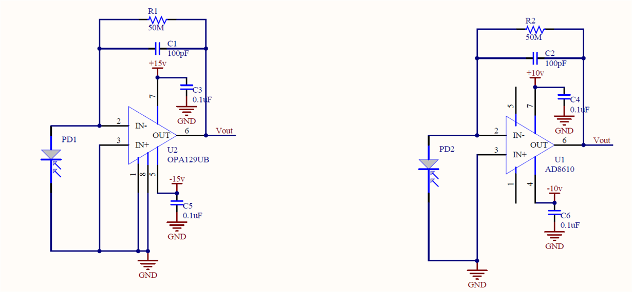
1.The following are the sampling circuits.As the instruments' lasers illuminate the dust, the dust scatters.At the same time, the photodiode receives the scattered light signal, and then the flash signal is converted to a voltage signal.This way, the concentration of the dust can be calculated by the size of the voltage signal being converted.

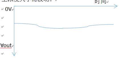
2. When the photodiode receives the scattered light signal, observe the state of the output signal of Vout as the voltage simulation shown below.When the concentration of dust is tested, the Vout's output voltage signal remains the same, otherwise the Vout will fluctuate with the dust concentration.

3. 

Dust concentration remained the same, if the environment temperature changes, Vout voltage value will change, this kind of phenomenon is problematic, will cause the instrument test values change with environment temperature change.

4. Present solutions

Select a small chip with Zero Drift parameters to replace, Zero Drift at OPA2187:0.005 mu V/s aC, if there is an effect to be tested.

5. Is there any solution?Please recommend, thank you!

  • Hello Jeffrey,

    Voltage offset drift with temperature is a normal error response for an operational amplifier. Indeed in some applications like yours it is best to apply an operational amplifier that has the lowest possible drift, while meeting all of the other requirements of the application.

    You mention the OPA2187 which has a very low drift of 0.005 uV/C. That definitely is a move in the right direction as far as drift is concerned, but it may not be optimum when it comes to other parameters that are important to your transimpedance application. The OPA2187 is a chopper op amp and although the input bias current is low on average, typically +/-100 pA, there are current peaks associated with the input chopping action. Since that input bias current flows through 50 Megohm feedback resistor there may be some evidence of the current peaks observed at the output. You may find that a non-chopper operational amplifiers having low drift produces a higher level of performance in your application than can be achieved with a chopper.

    Another operational amplifier that has low drift and isn't a chopper is the OPA2192. Its input bias current is typically +/-5 pA, and +/-20 pA max. Its maximum drift is typically +/-0.1 uV/C to +/-0.15 uV/C, and +/-0.8 uV/C to +/-1.3 uV/C max; depending on package type and temperature range. Not quite as low as that achieved with a chopper, but much less than the +/-10 uV/C maximum for the OPA129. I would recommend trying the OPA2192 in your application and see if the stability with temperature improves.

    You can find the datasheet for the OPA2192 here:

    Do keep in mind that the input bias current of the OPA2187 and OPA2192 is higher than that of the OPA129. The OPA129 is considered an ultra-low input bias current operational amplifier and is in a class with a few other operational amplifiers. If it turns out that is a critical parameter in your application, then we may have to find another amplifier.

    Regards, Thomas

    Precision Amplifiers Applications Engineering