This thread has been locked.

If you have a related question, please click the "Ask a related question" button in the top right corner. The newly created question will be automatically linked to this question.

TINA/Spice/ACF2101: ACF2101 & Virtual Ground?

Part Number: ACF2101
Other Parts Discussed in Thread: TINA-TI, , TLE2426, TLE2425

Tool/software: TINA-TI or Spice Models

Greetings,

I'm trying to get an ACF2101 set up for integration of a voltage signal, although that's not the recommended use of the product.

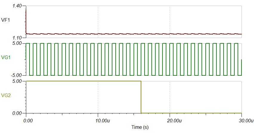
Using TINA-TI, I've imported the ACF2101m model and began playing with it. For logistics reasons, it is easiest for me to set up the power supply of the op amp with a virtual ground at 10V, where +20V goes to the V+ pin, GND goes to the V- pin, and +10V goes to the GND pin. My intent was to use the TLE2426 for the virtual ground, however there is no such model in TINA-TI, just the TLE2425. Regardless, attached is my current schematic. Although my hold pin is set to high (5V), which should place the chip in integration mode, no such thing happens. The resistor R1 is chosen to provide 100uA which should lead to a short integration time according to the datasheet.  Can anyone provide help? Attached is my SPICE model and relevant output.  acf2101broken.TSC
  • Hi Joseph,

    I suggest you try and get your AFC2101 circuit to simulate correctly with the recommended supplies and GND pin at ground, before attempting the 10 V virtual ground arrangement. I suspect that if GND is offset positively by +10 V than anything else that would normally be referenced to ground would also need to be lifted +10 V above ground.

    Some simulation models have internal nodes that are connected to ground (node 0). Often, they can produce unexpected behaviors when their supplies are connected in a manner other than the conventional way shown in the datasheet. I don't see any "0" connections inside the ACF2101 model so it may be okay to float its ground.

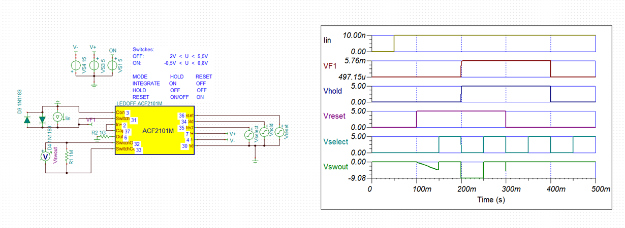
    The ACF2101 datasheet only provides Fig. 4 to help visualize the timing functions. Therefore, it may be a little more challenging to set them up correctly in a simulation circuit. I found a useful ACF2101 TINA Spice simulation circuit that was set up by one of our former Applications Engineers, Bonnie Baker, who did a lot of work on the device over the years. I am including it as a reference circuit so that you can see how she configured the circuit and set up the timing functions. I expanded the timing diagram which allows the various timing functions to be studied. You can see an image of this simulation circuit below.

    Regards, Thomas

    Precision Amplifiers Applications Engineering

    ACF2101bonnie.TSC