This thread has been locked.

If you have a related question, please click the "Ask a related question" button in the top right corner. The newly created question will be automatically linked to this question.

XTR108: The output current is unchanged for XTR108

Part Number: XTR108

Hi team,

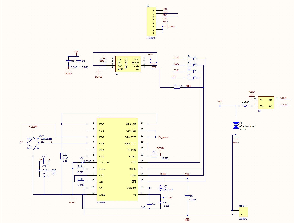
The customer is using XTR108. The current source output is configured to VI-0.

When the EEPROM data is not written, there is no current output.  When the customer writes the EEPROM data,

VI-0 can output 2mA current. And the 2mA current remains the same even if he changes  PGA parameters or the input signal.

The  sensitivity of the resistance bridge sensor is 2mv/v. The input differential voltage of the resistance bridge sensor is 0~10mV.

The input common voltage of the resistance bridge sensor is 2.5V.

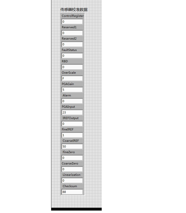
The attach is the customer's schematic and his EEPROM data. 

Would you provide some suggestions for the customer' issue?

Best Wishes,
Mickey Zhang
Asia Customer Support Center
Texas Instruments

  • Hi Mickey,
    Given the register contents you posted, I'd expect V/I-0 to be sourcing around 1.2mA. That would make the Vsensor voltage ~6.04V. Since the linearization constant is zero, this shouldn't change with changing input voltage. It looks like the bridge sensor's outputs should be connected properly to the internal PGA. Looking at the configured PGA gain (200x), and Rvi value (6.34k), I'd expect this configuration to output/draw ~19mA from the loop supply at full bridge loading. That current should be measured either at the supply (current into Vsup), or by inserting an ammeter at Header 2. Even at full output, the current out of V/I-0 should still be ~1.2mA, though.
  • Hello Alex ,
    Thanks for your quick reply!
    I still have problem with XTR108 which should output/draw ~19mA when I insert an ammeter at Header 2.
    I'd like you to answer these questions:
    1. can you explain why the V/I-0 should be sourcing around 1.2mA accroding to the register contents? I noticed 0.493mA with Rset=12.1k in the XTR108's datasheet. And I actrually got around 1mA from V/I-0 Pin.
    2. when the output of bridge sensor is 8mV, the ammeter at Header2 show 2mA, not ~19mA which I would be so glad to see. This is the main prolem. can you tell me the possible reasons or which way I should go to solve it.
    3. I am not sure whether my checksum is right, I just caculate it according to the datasheet. |Does it matter if the checksum is incorrect?
  • hi,can u help to urge your expert reply my question . this case is emergent
  • 1. Here’s my calculation: First, from the XTR108 datasheet:

    Substituting the formulae from table III, we get:

    In the register map you show, N11 is 0x50, and N10 is 0x01, making their decimal values 80 and 1, respectively. Vref is provided internally, and is 1.193V. Rset is 12.1k, as per your schematic.

    Plugging in all those values gives Iref1,2 = 616.3µA. Now, looking at the contents of register 9, we see that it’s set to 0x00. This means that both Iref1 and Iref2 will be connected to V/I-0 by the internal mux. This means that the actual current out of V/I-0 will be 2xIref1,2 or 1.233mA. If the register map you posted displays N10 and N11 as decimal values already, I’d expect the current to be 1.140mA. This current flows into R12, so I'd expect to see its voltage (and V_sensor) at about 6.04V.

    2. back-calculating the input voltage required for a 2mA output, I get an input voltage of -1.34mV. For the V to I stage of the XTR108, I calculate that a 253mV output from the PGA would yield this current, which is very close to the minimum output swing of the PGA. Have you tried switching your PGA’s polarity? Writing 0x32 to register 8 would do this.

    3. It looks like your checksum is right. When I calculate it from the register contents, I come up with the same value as is in register 15. Additionally, register 0 is 0x00, meaning that the CSE bit is cleared. If the checksum were wrong, though, I’d expect the output to be around 1.77mA, as the datasheet indicates that the XTR108 will program itself to the lowest under-scale level in this event. 

  • Hi Alex ,
    I am very grateful for your help!

    About the question1, I agree with your caculating but I got the same Iref1,2 output at Pin V/I-0 no mater what value I write to the register 9 0x00 or 0x10 or 0x01. I got no output at pin V/I-0 if I write ohter value to register 9. So I asume that my setting has been writen to EEPROM and read out by the XTR108. This performace confused me. Can you think about that and give me more direction?

    About question2, I have reversed the V/I-2 and V/I-3 to the PGA and just got same result. But a funny thing happened when I fed a 1.5v input to V/I-2 and V/I-3 by mistake, I measured 10.70mA at the meter, and when I adjust the input voltage the meter read out 10.6mA~ 10.8mA! looks like the PGA is not working properly. The output just always kept 2mA if the input to V/I-2 and V/I-3 is around 8mV .

    Looking forwards to your comments

    Best Regards,

    Leo Zhao
  • Hi Leo,
    I should have asked before, have you tried this testing with the RBD bit set to 1? That should prevent the XTR108 from refreshing its register settings from external EEPROM before the EEPROM is programmed.