This thread has been locked.

If you have a related question, please click the "Ask a related question" button in the top right corner. The newly created question will be automatically linked to this question.

LOG114EVM: Problems with linearity of the evaluation module

Part Number: LOG114EVM
Other Parts Discussed in Thread: LOG114, , LOG104

Hi TI employees,

for a student project, i have to measure the resistance of wood over 8 decades as a function of moisture. Because of the high resistances and the logarhytmic behaviour of this material, i decided to use the Log114. I bought the Log114EVM and measured the input current as seen in figure 11 in the datasheet:

I used a 24V voltage source and the resistances had a range of 1MOhm to 1TOhm to simulate the wood resistivity. in addition, i changed R11 from 1MOhm to1GOhm on the EMV to get a higher ratio of I1 to I2.
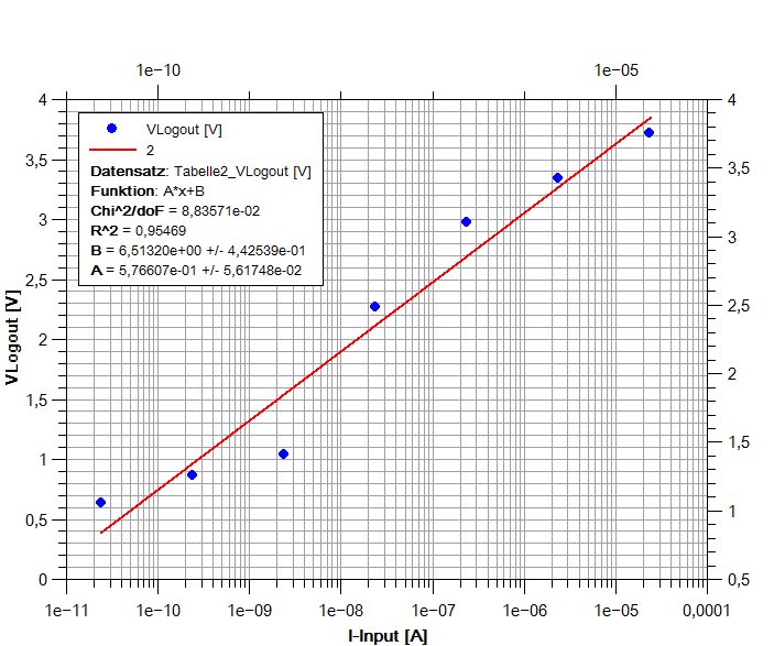
I plotted the Vlogout and was a little bit surprised because of a non-linearity of the voltage as you can see in the next picture:

Do you have any idea why there is such a harsh notch at about 2.5 nA ? Is it a problem with the Log114 or did i choose the wrong measuring method? I checked my resistances, they seem to be correct.
I also simulated the EMV and there is no such problem.

Hope you guys can help me. If you need additional information, please let me know.

Kind regards
Felix

  • Hello Felix,

    The LOG114 EVM was designed for use from 10 nA to 10 mA, as stated in Section 2 of its User's Guide. It isn't that the EVM can't be used for currents lower than 10 nA, it just hasn't been characterized at those levels. There may be something about its construction that limits the accuracy below 10 nA levels.

    An issue often overlooked when operating a circuit at very low current levels is cleanliness. We often find that residual solder flux remaining on the PC board surface after soldering provides leakage currents paths that can rival the intended current levels corrupting the results. We suggest using water soluble flux for any fresh soldering done to the LOG114 EVM board, followed by two complete cleaning cycles with fresh DI water, in an ultrasonic cleaner. Make sure what ever drying method is used doesn't recontaminate the board.

    Alternation of the 1 Meg to 1 T precision resistor values due to handling methods can occur. Our skin is covered by a fine layer of oil that has conductive properties. This oil can be transferred to the resistor outer surface and it forms a resistance that is parallel to the resistor's resistance. Subsequent handling alters the resistance by redistributing the surface oil. It is best to handle the very high resistance resistors with clean, sterile synthetic gloves. If the resistor surfaces become contaminated they should be properly cleaned.

    Additionally, the LOG114 transimpedance gain can become very high at low current levels. Low-level induced noise, such as 50/60 Hz line noise can contaminate the intended currents. You may find that enclosing the EVM board inside a metal box, using a battery to power the LOG114 circuit that is internal to the box , will help reduce the induced noise. It is also recommended that the external connection circuit to the resistors, or piece of wood, be accomplished using a quality, twisted pair cable.

    Regards, Thomas
    Precision Amplifiers Applications Engineering
  • Hello Thomas,

    thanks for your helpful and detailed response. I followed some of your instructions such as the twisted pair cables, the noise reduction and cleaning the board from residual solder flux. In addition, i measured all of my test resistances with a TOhm meter and they were all correct.

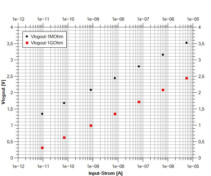
    I still have the problem shown in the illustration above, because of the limitation of the input current to 10nA you talked about. My question is now: where does this limitation come from? I can't find an answer in the circuit of the EVM. Can you suggest me any solutions to usethe board with a range of 100pA to 10mA? Or can you suggest me another circuitry with the Log114 where this current range is possible ?

    Thank you in advance for your help

    Regards,
    Felix Pfeffer

  • Hi Felix,

    It is difficult for us to know why you are having the particular problems with the LOG104 EVM you have mentioned. I didn't design the LOG114 EVM so I don't know why it was designated for use down to 10 nA, and not lower. It might have something to do with the PC board material, or a less than ideal layout that has unknown leakage current paths.

    The LOG114 datasheet states in Figure 1, Dual Supply Configuration Example for Best Accuracy Over Eight Decades. That may be a a better circuit option to try. It would require laying out a new board, but then you would have control over the design of the board. I suggest identifying a very low loss PC board material to use for the board to minimize leakage currents and using it instead of FR4. The other points I mentioned in the previous response would need to be observed as well.

    Regards, Thomas

    Precision Amplifiers Applications Engineering

  • Hi Thomas,

    Finally I'm able to measure currents lower than 10nA with the LOG114 EVM.

    I used a perfectly shielded case, twisted pair cable and supplied the circuit with batteries. In addition, I placed a 1st order lowpass at the output of the opamp to supress the mains hum.

    Thanks for all of your tips, they helped me a lot.

    Best regards,
    Felix

  • Hello Felix,

    Congratulations on resolving your LOG114 measurement issues; the log conformity results look very good. Good luck with your project.

    Regrads, Thomas

    Precision Amplifiers Applications Engineering