This thread has been locked.

If you have a related question, please click the "Ask a related question" button in the top right corner. The newly created question will be automatically linked to this question.

TINA/Spice: 2nA to 100mA Constant Current Source - design suggestions ?

Other Parts Discussed in Thread: TINA-TI, OPA209, OPA2140, OPA1622, OPA627, OPA140, LMC6001, DAC8718

Tool/software: TINA-TI or Spice Models

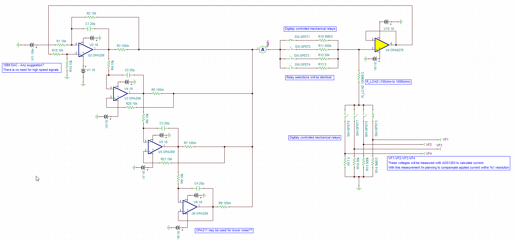
You may find my design. I used 4 parallel op-amp for higher current supply.  There is no problem with TINA simulations. 

my plan is changing current range with relays. Resistor values may change to compensate current range. I'm also planning to measure applied current to compensate leakages. 

Paralleling 4 op-amps will reduce noise or not? 

Is this possible to get %1 accuracy? 

Any suggestion to improve my design? 

How will opa209 output leakage current affect my precision?

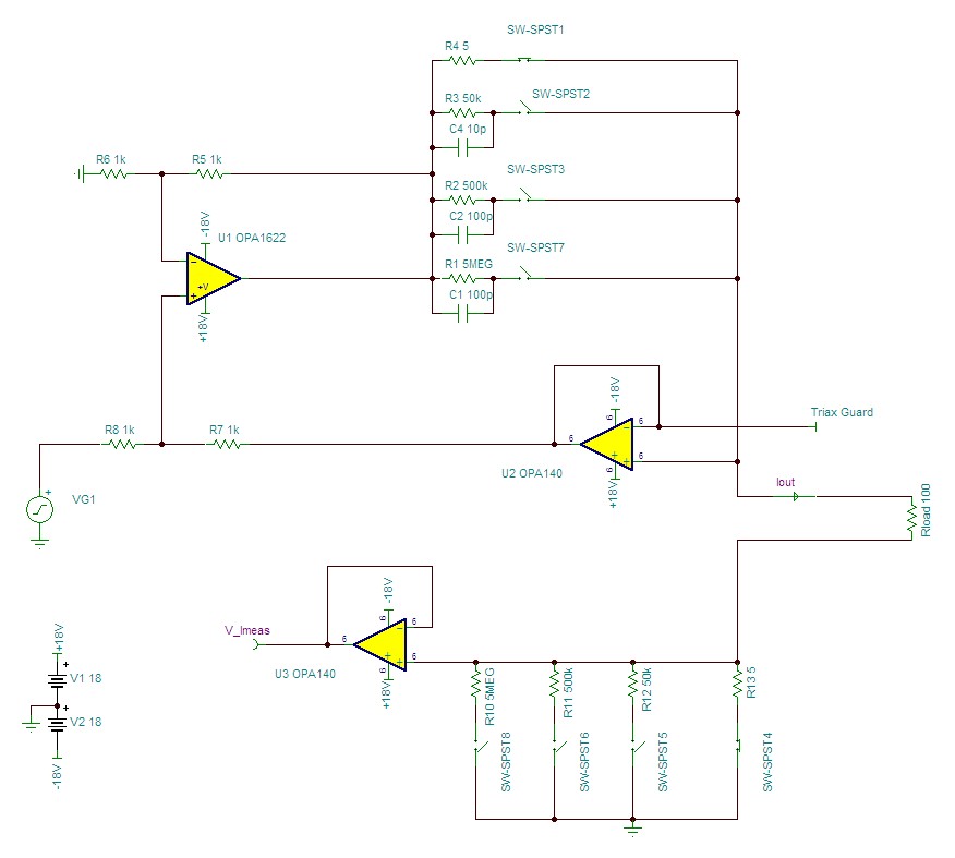
Also, I want to use triax connector for current output(R_LOAD). How can I drive inner shield of triax(Guard)?

  • Hi Koray,

    I am glad you don't have any problem with TINA simulations. Since you questions are application specific with specific parts in mind, I will be moving your post to different E2E forum where folks over there will be able to help you further.

    Herman
  • Hi Koray,

    1. Paralleling multiple amplifiers will average down the noise of the paralleled op amps by a factor of 1/sqrt(n). In this case, however, the input current noise from the master amplifier (U2) largely dominates the overall noise at lower gains, with resistor noise becoming dominant at lower current settings.
    2. It may be possible to reach 1% accuracy. Doing so will, at minimum, require use of .1% tolerance resistors throughout the circuit. Additionally, matching (particularly of temperature coefficients) will be very important.
    3. I'd recommend a few changes. First, I'm not certain by inspection that the master-slave op amp configuration you've drawn will split currents evenly across the 4 amplifiers. A first-glance look at it makes me think that the bottom two amplifiers will source most of the current. I'd recommend a design like the following:

      This uses an OPA1622 as the main amplifier in the current pump. The OPA1622 should be capable of driving 100mA without assistance, and with relatively low voltage noise (2.8nV/√Hz). I dropped the 10kΩ feedback resistors to 1kΩ both to reduce resistor noise and to reduce the impact of U1's input current noise. I swapped an OPA140 (I'd use a dual, the OPA2140, for U2 and U3) for the OPA627, though the OPA627 could certainly be used in this application. U2 serves double-duty in this application, both as the feedback buffer for the current pump, and as the guard driver for the Triax cable. U3 was added as a buffer ahead of the ADC, as low current ranges (especially with high impedance loads) would likely have too low of an output impedance to adequately drive an ADC. 

      In order to get a good transient response and reasonable stability, I had to add C1-C4 in parallel with the higher range resistors. These values appear to give decent step responses into resistive loads, but I'd double check stability into reactive loads.

    4. Output current leakage shouldn't be too much of a concern here, but especially down at 2nA, input leakage of buffers and parasitic leakage on the PCB will become a big issue. In fact, while OPA140 and OPA826 should work very well at room temperature (~5-10pA of input bias current), at 125°C, both will leak 2-3nA. If this is an issue, you might consider replacing both U2 and U3 with something like the LMC6001. While this would reduce the compliance range of the current source (LMC6001 has a 15V maximum supply), LMC6001's input bias current is 25fA at room temperature and 2fA over the full temperature range. This does also make a tradeoff in noise: LMC6001's voltage noise is 22nV/√Hz vs. 5.8nV/√Hz for OPA140. 
    5. For the Triax guard driver, I'd use the output from U2. This should also be used as the source for a guard ring around the entire Iout node when doing layout of this design.


    You can download the TINA-TI file I used for the transient analysis here

    One further note: I connected the voltage source for the input to R8, rather than R6. This shouldn't affect the overall stability of the circuit, only polarity of the output current. If your application needs a negative output current for positive input voltages, simply connect the voltage source to R6 and ground R8. 

  • Thanks for suggestions Alex.
    I'll use this circuit and then I can share measurement results.

    BTW, do you have any suggestion for DAC ?
  • Hi Koray,
    The choice of DAC will depend on performance goals. What sample rate and resolution were you considering? Any restrictions on bus type?
  • Hi Alex,

    Any type of serial interface is OK.

    My goal is %1 resolution in all current range. This current source will perform as a DC. There is no need for high-speed DACs.

    I think that using 16-Bit(or higher) DACs within +-5V range might be enough.  (DAC8718)

    BTW, there are no many options for higher resolutions within +-5V range.