This thread has been locked.

If you have a related question, please click the "Ask a related question" button in the top right corner. The newly created question will be automatically linked to this question.

OPA4192: Bainter notch filter real design Q

Part Number: OPA4192
Other Parts Discussed in Thread: TINA-TI

Hello!

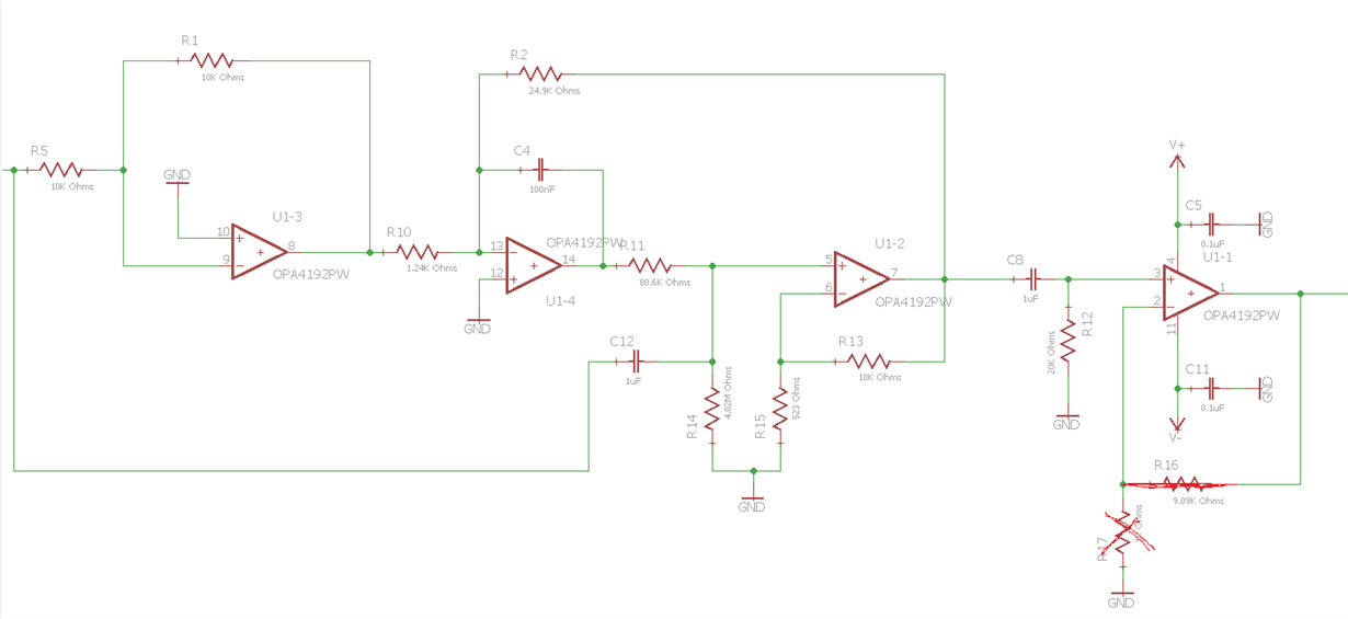
I made notch filter with Bainter topology (using  OPA4192) and obtain low Q.

Webench calculation gave ~40db, SPICE too, but I have only attenuation 4-5 times in stopband.

Frequency is low - 40-50-60 Hz, ground is.

Than I try change resistors - it gave frequency shift, up and down left and right passbands... all as in simulation...

Are anybody work with bainter filter? What is about real Q ?

Thanks!

  • Hello Iurii,

    Thank you for posting your question on the E2E Forum. An applications engineer from the precision amplifier team will be able to address your post during standard business hours.

    Best regards,
    Errol Leon
    Texas Instruments
  • Sorry! I see smooth plot and ask about Q, but my problem not with Q itself.
    I obtain low attenuation in stopband ((.
  • Hi Lurii,

    If you can provide us a complete schematic of your Bainter notch filter, and the details of your filter specifications such notch frequency, gain, notch depth, response type, etc, we can check and make sure that it is being correctly implemented. Also, we need to know the tolerances of the components you are using in your notch filter circuit. It is very easy to ruin the filter performance if the components used are not accurate.

    Regards, Thomas

    Precision Amplifiers Applications Engineering

  • All resistors are 1%, capacitors are 5% ceramic.
  • Hello Lurii,

    I copied your Bainter 50 Hz band-stop filter into our TINA-TI simulator. You can see the results obtained from the simulation below. The filter topology appears to produce an accurate notch frequency, but poor notch depth - at least with the particular filter parameters slected for this case. It appears to achieve only 13 dB of attenuation at 50 Hz. There may be some filter settings you could set differently such as the -3 dB bandwidth and the stop-band bandwidth, to achieve better notch depth.

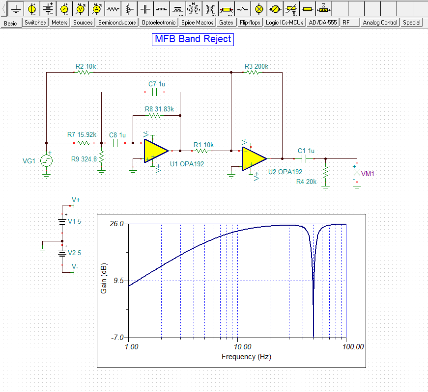
    There is an older TI filter synthesis program called FilterPro. It uses a couple of different band-stop typologies than Webench Filter Designer's Bainter topology. I synthesized a simple 2nd-order, 50 Hz notch filter using its Multiple-Feedback (MFB) topology. It is simply an MFB band-pass topology that inverts the input signal polarity and then sums it with the original bandwidth input signal. The result is the band-pass response that gets subtracted from the original signal bandwidth and a band-reject response is the result.

    You can see the results here:

    The notch depth at 50 Hz is on the order of -33 dB. Note that this notch depth  is achieved with exact components and tolerance variations will affect the actual depth.

    Regards, Thomas

    Precision Amplifiers Applications Engineering

  • Thanks! This is comprehensive answer for my issue!
  • Hi Lurii,

    Glad to assist - good luck with your filter project.

    Regards, Thomas

    Precision Amplifiers Applications Engineering

  • But that about to increase number of points in TINA simulation? 100 points give 13 dB but 2000 give more 30.
  • HI Lurii,

    Increasing the number of samples in the simulation provides higher resolution. I always use a number like 500, or higher, and 500 was the number I used to get the -13 dB attenuation with the Bainter circuit. Since the greater notch depth is ~- 30 dB with 2000 samples, then the circuit is capable of that performance. But keep in mind that notch depth is very, very narrow and will only be achieved with exact component values. The notch depth will quickly degrade if wide tolerance components are used.

    Regards, Thomas
    Precision Amplifiers Applications Engineering