This thread has been locked.

If you have a related question, please click the "Ask a related question" button in the top right corner. The newly created question will be automatically linked to this question.

INA163: Regarding circuit diagram

Part Number: INA163
Other Parts Discussed in Thread: TINA-TI

Hai,

I have developed a six channel mixer circuit, I got an small issue in this, I need a high gain and low noise op-amp , i have selected INA163 ic as a pre-amplifier. Can any one provide me circuit for pre-amplifier using INA163 ic. Such that it reduces the noise and gives the perfect mixer output.

Thanks & Regards,

Prasad.

  • Hi Penchala Prasad,

    A few questions:

    1. Could you provide a schematic for what you're considering?
    2. Is this mixer intended to be used with differential inputs or single ended signals?
    3. If you intend to use this with microphone-level inputs, do you need to support phantom power delivery?
    4. What input signal levels are you working with, and what output level do you need?
    5. Do you need single ended or differential outputs? 

  • Hai Alex Davis,

    Following are the requirements:

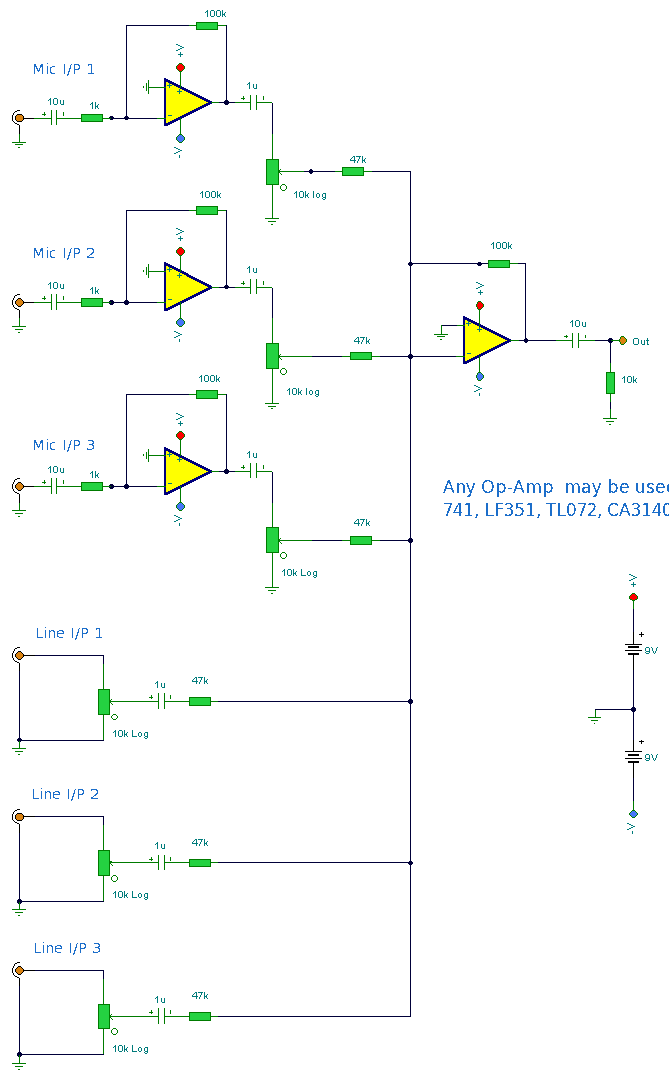
    1. Here is the circuit diagram for 6 channel mixer which i have used.


    2. It is used for single ended input signals.

    3. Yes, i am using phantom power supply too.

    4. I am using AM-U-755 dual wireless micro phone and condenser mic (TAKSTAR CH982)

    5. I need differential output's.

    The actual problem is everything is ok with the mixer but, i am getting noise problem so that i need a very good pre-amplifier with high gain and low noise. So,i selected INA163 for that purpose, Now i need the circuit diagram for microphone pre-amplifier. Can you help me out.

    Thanks & Regards,

    Prasad.

  • Hi Prasad,

    For a single-ended input as shown, an INA163 may not be necessary. In this case, I'd suggest the following:

    Right now, I suspect that your noise performance is dominated by the large resistor values chosen, so the first suggestion I'd make is to lower those by at least 10x, as above. Using these values with an inverting topology will excessively load the inputs, so I've redrawn the circuit as a noninverting amplifier. R3 provides a return path to ground for the op amp's input bias current, while R4 and C2 form a low-pass filter to suppress EMI received at the mixer's input. 

    C1 provides DC blocking at the input, with R10 isolating the phantom power source from the input in case of a short circuit. SD5 and SD6 clamp the voltages seen at the op amp's input to protect it in the event of a short circuit at the mixer input. 

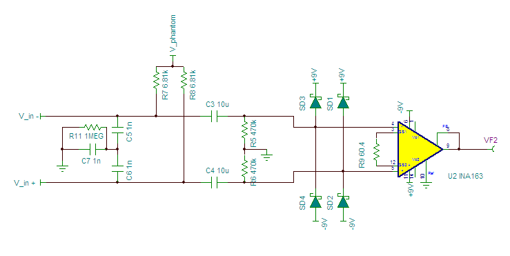
    Most professional systems will use a balanced input, such as an XLR connector, for their inputs. In this case, I think the INA163 is a good choice, and I'd recommend the following circuit:

    In this case, C5, C6, and C7 help to suppress EMI at the inputs, R11 was required for simulation to provide a DC path to ground for those 3 capacitors. R7 and R8 provide a load resistance to the input, and inject phantom power. For pro audio applications, V_phantom would typically be ~48V. C3 and C4 provide DC blocking, R5 and R6 provide a DC path for the INA163's bias current. SD1-SD4 clamp any transients to the supply rails to avoid damage to the amplifier. 

    For a gain of 100 Rg on the INA163 should be 60.606. The closest standard resistor value I could find was 60.4 ohms, which gives a gain of 100.3. 

    For either circuit we recommend placing TVS diodes on both supplies to absorb any supply transients and prevent damage to the circuit. In this case, with 9V supplies, a 10V TVS unidirectional TVS diode should be used from each supply to ground. 

    I'm including a TINA-TI simulation file which contains both circuits. You can download it here.