This thread has been locked.

If you have a related question, please click the "Ask a related question" button in the top right corner. The newly created question will be automatically linked to this question.

LMP7721: Dual supply operation

Part Number: LMP7721
Other Parts Discussed in Thread: LM27762, IVC102

Are there known issues operating this chip with +/- 2.5V supplies instead of a single rail 5V supply?  I assumed it would work with dual rails provided the total differential voltage was within limits, but now I'm not so certain.

My supplies come from a LM27762, and I am seeing a lot of noise on the output of the LMP7721 that has been amplified from the supply rails.  The PSRR spec of 92dB is specified for a single rail supply, and it has made me question if attempting to use dual rails is the source of the trouble.  I'm using the LMP7721 as a current integrating preamp in the following configuration, so the gain is fairly substantial:

  • Hello Adam,

    Your circuit should work fine. Your common-mode is centered, where the leakage is the lowest.

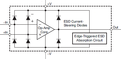
    The problem is that, despite the AC CMRR specification, noise has another way to get into the signal path, and that is through the capacitence of the ESD protection diodes that are on ALL the inputs and outputs.

    Normally a fraction of a pF to the supplies is not a problem, but when dealing with very high impedance, and high frequency noise, the capacitance of the ESD diodes provides an AC path that bypasses the natural PSRR.

    You were on the right track to add RC filters to the supplies. If the load on the output is light, try increasing the side of the resistors to 100 ohms or more - maybe 470 and increasing the capacitor to as large as you can fit (>100uF). This should knock down the noise on the supplies significantly.

    Also watch for any points where the input trace can "see" the supply lines.
  • Thanks, I'll give that a shot.  The load should be minimal, as it only feeds subsequent gain stages. 

    Is the noise via the ESD diodes something unique to this part?  A previous version of this design made use of an IVC102 running off of +/- 15V supplies with worse PS noise, and almost nothing coupled through the pre-amp.  I'll keep an eye on how much the supply resistors drop the voltage at the chip.  Full output range isn't super critical in this stage, but the closer I can get to it the better.

  • Hi Adam,

    It is common for CMOS op-amps to have ESD protection, due to the much lower gate breakdown voltages.

    Below is the common ESD protection scheme for CMOS amps. Pretend each diode is also a 0.3pF to 0.5pF cap and you can see the paths. For reference, the Xc of 0.5pF at 20kHz is 8 Megohms....

    Older JFET based devices may not have these ESD diodes ,as the older high voltage JFET/Biolar devcies tend to be a bit more "rugged".

    I am not familiar with the IVC102 internals, but at 30V, it is most likely a JFET-based device and may not have these ESD input diodes.

    So for very low current measurements, you really want to keep the supplies clean, possibly dedicating a separate filtered supply for the front end amplifiers (using R, C and even L's and  ferrite beads). Also watch out for power supply traces running under signal paths.