This thread has been locked.

If you have a related question, please click the "Ask a related question" button in the top right corner. The newly created question will be automatically linked to this question.

INA125: Is this bridge sensor can work with this amp?

Part Number: INA125
Other Parts Discussed in Thread: LM7705

Hello,

I'm using the INA125 with a load cell and it works good. 

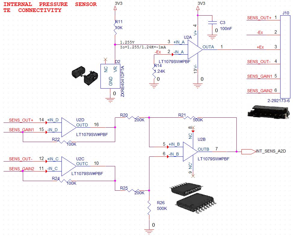
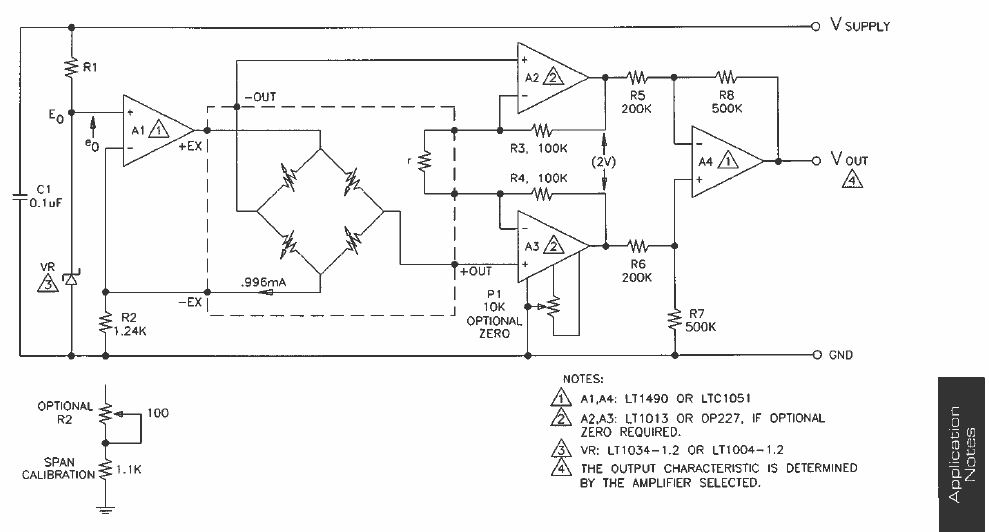
Now i have another sensor which using the bridge method - but a little bit different -- it is an industrial pressure sensor like in the below link:

I'm already using the INA125 and I want to use the same chip for this sensor. is the INA125 will work as it should with this kind of sensor?

Thank you very much.


  • the sensor is
    86
    Compensated [TE Connectivity]

  • Hi Itay,

    The file in your first post does not seem to have gone through, but provided your pressure sensor is biased within the common-mode limitations of the INA125 and produces a differential voltage then there shouldn't be any issue interfacing with the sensor. If the impedance of the bridge is excessively large, then you may run into additional error from the bias current of the INA125, but this is 25nA typical so this shouldn't contribute anything significant. Let me know if you run into any issues!
  • Hi Jak,

    Thank you for the fast replay,

    ENG_DS_86C_A5.pdf

    I try to upload the spec again.. I noticed that in the load cell the spec talking about supply voltage and in the pressure sensor they are talking about supply current.

    I know that I can just put a resistor in series - but beside that, is it something that I should concern about?

    thanks  

  • Hi Itay,

    Yes it seems that all of the specs they give for the pressure sensor assume an accurate constant current source. You will want to create an accurate current reference for this. I believe the input resistance spec pf the sensor gives the bridge resistance seen by the source, and this can fluctuate from 2.5KOhms to 6.5kOhms. Assuming a constant 1.5mA source, your bridge voltage will be somewhere between 3.75V and 9.75V, meaning the common-mode voltage at the inputs of the INA should be somewhere between 1.875V and 4.875V. You need to make sure you have sufficient head room on your supply for this.
  • Hi Itay,

    the datasheet of pressure sensor is rather confusing. Does "input resistance" mean the resistance of bridge legs and "output resistance" the gain resistance?

    Well, if a constant current excitation of 1.5mA is needed you cannot work with a series resistor. Instead, you must provide a precise constant current of 1.5mA, because the voltage drop of this current across the bridge legs directly affects precision and linearity of your measurement.

    If the excitation current has to be 1.5mA to develop a full span measuring signal of 100mV across the bridge, then the resistance change of bridge legs is in the order of 100mV/1.5mA = 67 Ohm. Am I right? Whether the INA125 is suited, depends on your accuracy needs. Provided that you can calibrate out the offset voltage at zero pressure, then only the input offset voltage drift, the input bias current drift and the input offset current drift have to be taken into account.

    Kai
  • Hi Itay
    We haven't heard back from you, so we assume you were able to resolve your issue. If not, just post a reply below or create a new thread if this one has locked due to time out.

    Thanks
    Dennis
  • Sorry for the late response, 

    I'm not fully understood from the answers if it will works.

    This is my current design:

    which i know it will works, but the INA125 will make my design much easier... 


  • Hi Itay,

    looks like you drive the sensor with a constant voltage and not with a constant current? But datasheet of sensor has all the data specified for a load current of 1.5mA. I guess you must drive the sensor with a constant current source pushing a current of 1.5mA through the sensor bridge.

    Have you contacted the manufacturer of sensor? What does he mean? Can he give you a schematic which shows how the sensor has to be connected?

    Kai
  • Hi Kai,

    This is from TE application note:

    the input current can be calculate from this formula:

    I also added the application note for more details.

    thanks 

    APP-101_1 (002).pdf

  • Hi Itay,

    ah that's nice! And now you want translate this circuit into a circuit using the INA125?

    Kai
  • Hi Kai,

    The sensor is a bridge - the INA125 expecting for a bridge sensor ... So what I asked is if they can work together... from your answer i guess that the answer is no.

    thanks
  • Sorry Kai,

    I did read you response as i should...

    I would like to use the INA125 because i'm already using it in the project and it is much easier to work with.

    thanks
  • Hi Itay,

    This is certainly something you can do with the INA125, and you can even implement the current reference with the onboard regulator. The key concern is going to be that you scale your supplies appropriately so that you remain with the input/output limitations of the device. While we do not have a true model for the INA125, I have attached a rough equivalent showing how you could configure everything. I would recommend placing a bipolar npn transistor connected as an emitter-follower on the output of the reference buffer to make sure it doesn't struggle to source the 1.5mA that you need (we don't actually have the output current specified but I believe this is right around the limit of its current sourcing capability). The actual bridge impedance will dictate how large of a positive supply you need. If we assume 6.5KOhms (the upper range of what was specified), then at 1.5mA the bridge voltage is 9.75V. Adding ~0.7V for the base-emitter drop on the transistor and about 1.5V for headroom on the reference you would want to use a supply of at least +12V. INA125 Model.TSC

  • Thank you very much Zak, 

    I've all the components that I need in my lab, I'll check it out.

    BTW, if you think that it can be done without the needs of the negative voltage please let me know - it will make my design much easier and cleaner.

    thanks you 

  • Hi Itay,

    can you measure Rg of your sensor?

    Kai
  • Hi Kai,

    6K Ohm
  • Hi Itay,

    can you carefully heat up a bit the sensor by the help of a hair dryer? Do you see a change of resistance of Rg?

    Kai
  • Hi Itay,

    While it is not entirely clear, it seems to me like your sensor is only going to output positive differential voltages. This means you won't need to swing large negative voltages on the op-amp, but you will still need to do one of 2 things to have a valid output at low bridge voltages:

    1) Use a small negative supply. You could use a device like the LM7705, which generates a -230mV supply from a +5V input. This gives you enough room on the low end to properly read small pressure levels. OR

    2) Bias the INA through the reference pin. If you choose to implement the current source with the onboard regulator then you would need to use another regulator for this reference voltage. Note that the output will shift by the reference voltage as well, so to get the true output voltage your load would need to be connected between the reference and the output as shown in figure 6 in the datasheet.
  • Hi Itay
    We haven't heard back from you so we assume this resolved your issue. If not just post another reply below (or create a new thread if this one has timed-out).

    Thanks
    Dennis
  • Thanks Zak,

    I'll try it and update soon as i get results.

  • Hi Itay
    We haven't heard back from you so we assume this resolved your issue. If not just post another reply below (or create a new thread if this one has timed-out).

    Thanks
    Dennis