This thread has been locked.

If you have a related question, please click the "Ask a related question" button in the top right corner. The newly created question will be automatically linked to this question.

OPA547EVM: using OPA547/OPA 548 Evaluation Module as a current amplifier

Part Number: OPA547EVM
Other Parts Discussed in Thread: OPA547, TINA-TI, OPA548, OPA551, OPA548EVM,

Hello,

I am a mechanical engineering student, and I considering using the OPA547/OPA 548 Evaluation Module as a current amplifier, the input will be  1 kHz 1 V low current from a function generator and the output will be  1 amp the exit impedance is around 1 ohm.  I have 2 main questions

1. can I use the  Improved Howland Current Pump Configuration Setup  in order to answer my experiment needs.

2. the user guide has a BOM table, does everything in the BOM table is coming as a part of the package of the module?


thank you 

Alex Kolomisky.

  • Hi Alex,

    I'm not sure what you mean by "exit impedance." Do you mean you are driving a 1 Ohm load?

    You can certainly use an improved howland current pump configuration, but it really depends on the accuracy you need and what you are driving. As a rule of thumb, with 1% accurate resistors around the pump you can expect a worst case error in output current of about 10%, 1% with 0.1% resistors and so on. The Howland current pump can drive capacitive loads very well, but you have to be careful if you are driving an inductive load.

    For the evaluation module, everything in the BOM will come populated on the board, except for components listed as DNP or DNI (do not populate/install).
  • HI 

    Thanks for your answer! I am planning on using 0.1% resistors.

    another 2 questions:

    1) what is the bandwidth(1 ohm load, 1 ampere exist, 1 Volt input)?

    2) and I am driving a inductive load of around 0.00005 F, which will be around 0.3 in 1 KHz, the other  0.7 ohm will be simple resistor.will it be a problem?

    are there other molduls that fit my needs?

    low current, 1 V input (1-10 KHZ) and 1 ampere output and 1 ohm load?

    Alex.

  • Hi Alex,

    the Howland current source is tricky and can become instable relatively quickly, because it contains a path of positive feedback.

    Here's a nice application note about it:

    www.ti.com/lit/an/snoa474a/snoa474a.pdf

    In any case, carry out a simulation with TINA-TI first, to check the stability of your circuit.

    Kai
  • Hi Alex,

    Regarding your questions:

    1) what is the bandwidth(1 ohm load, 1 ampere exist, 1 Volt input)?

    For any operational amplifier application, including the Improved Howland Current Pump, it is important to have sufficient open-loop gain (Aol) available at the maximum frequency of interest. You indicate the input signal frequency will be 1 kHz and according to datasheet Figure 1 - Open-Loop Gain and Phase vs Frequency, there is about 60 dB of Aol at that frequency. That should be sufficient to help keep gain-related errors low.

    2) and I am driving a inductive load of around 0.00005 F, which will be around 0.3 in 1 KHz, the other 0.7 ohm will be simple resistor.will it be a problem?

    If your load is highly inductive that can be a problem for the Howland Current Pump. The phase between the voltage and current split by the complex impedance consisting of R and L. This compounded by the pump's use of dual feedback and the amplifier's open-loop output impedance (Zo) can create a condition where the phase margin is very low or drops to zero. Transient behavior would suffer and the possibility for instability could exist. If you have a more complete description of the load that would be helpful. This has to analyzed as a complete system.

    Regards, Thomas
    Precision Amplifiers Applications Engineering
  •  Hi Thomas,

    Thank you for your answers!

    The load is a quite simple one. it consists from a solenoid with 0.00005H inductance and Resistor of 1 OHM serially connected. The stability of the phase margin is extremely important to me. I can change the load - but not by scale (I can replace the resistor to up to 5 Ohm resistor). 

    The solenoid is a strain sensor we developed, the changes it's inductance when mechanically loaded. 

    will the system be stable? is there another alternative?

    P.S

    I didn't find the 547/548 opa in TINA.

    Alex.

  • Hi Alex,

    you will find the model of OPA548 in TINA-TI in the "spice macros". Or open the "reference design" which you will find on the OPA548 product page.

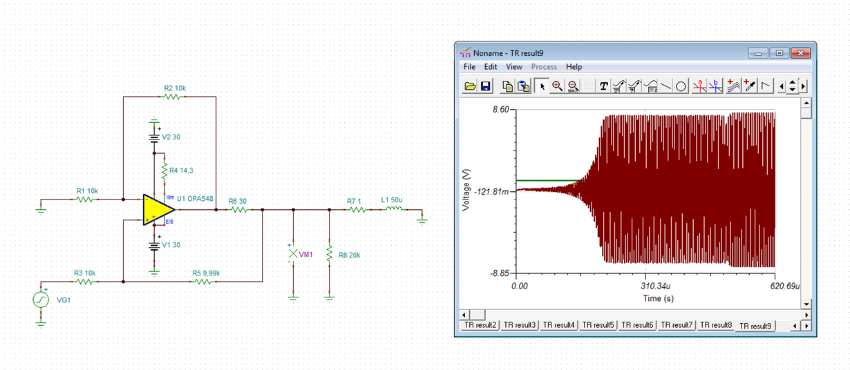
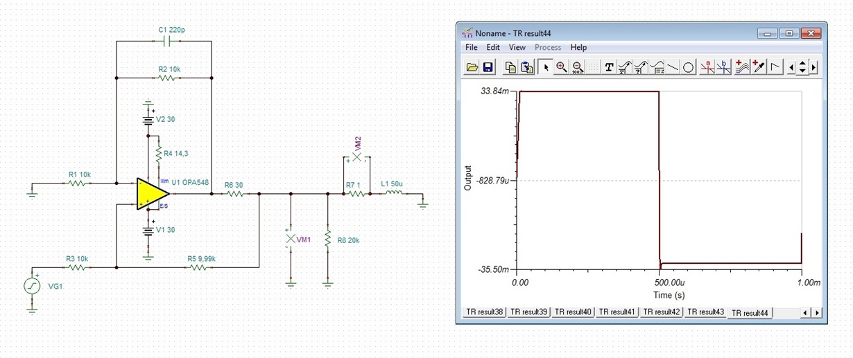
    I have simulated your circuit. The input signal is a 1Vp 1kHz square wave. As I have expected, the circuit is instable:

    Kai

  • Hi Alex,

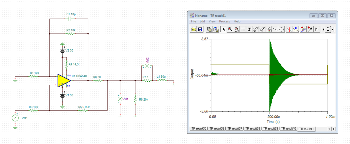
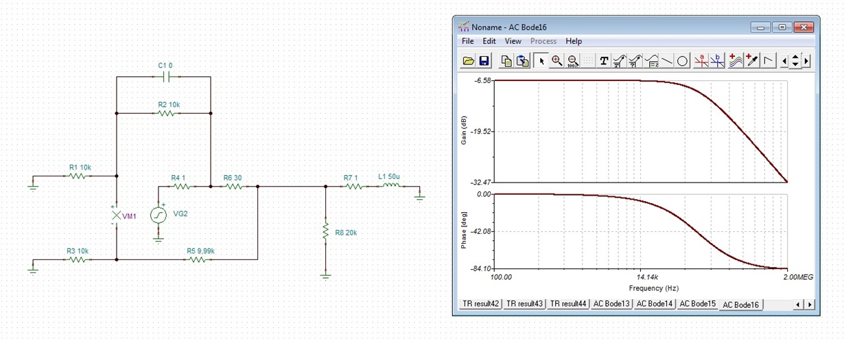
    the phase analysis shows that the phase margin is totally eroded. That's the cause of instability. By adding a feed forward capacitance (C1) a phase lead compensation can be accomplished, which makes the circuit stable again. At least the oscillating can be prevented. But the circuit still shows some ringing:

    VM1 is the dark green graph. VM2 is the brown graph.

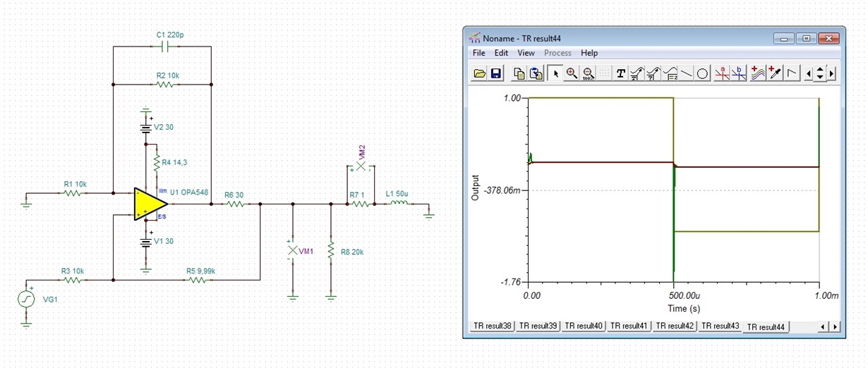
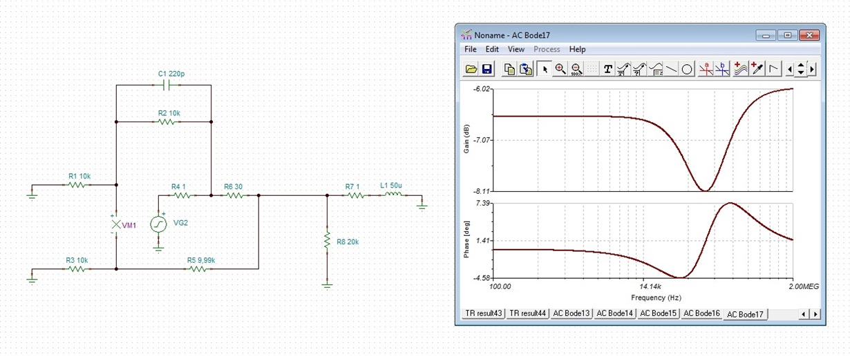
    Below you will see how I make a phase margin analysis. R4 presents the open loop output inpedance, which I do not exactly know, by the way. VM1 measures the voltage between the two inputs of OPA548. In the phase margin analysis I'm interested in the phase difference between the intrinsic output voltage and VM1. Without feed forward capacitance the phase difference goes down towards to -90°. So, the phase margin of OPA548 is nearly totally eroded. See figure 1 of datasheet. With 220pF feed forward capacitance the phase difference is much less and is limited to about -5°. So, the OPA548 has enough phase margin to work stable:

    Kai

  • Hello Alex,

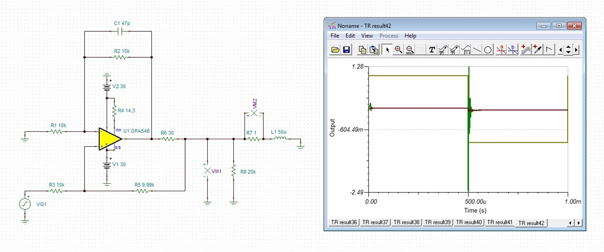
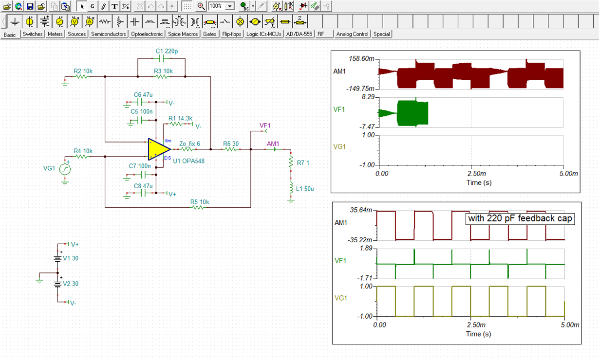
    Kai is correct - your Howland Current Pump circuit without compensation is unstable. I ran your circuit in TINA using a slightly modified OPA548 model that corrects the open-loop output impedance (Zo), and I obtained nearly the same results that Kai did. The scheme he devised using the 220 pF capacitor across the negative feedback resistor appears to compensate the circuit sufficiently. You can see the TINA simulation results below with and without the 220 pF feedback capacitor.

    The peak current in you applicaiton is only about 35 mA so the OPA548 has much more output current capability than is needed. The OPA547 is rated for 500 mA, and the OPA551 is rated for 200 mA. The latter is offered in smaller package types. If you decide to use another high-voltage op amp, the compensation should be revaluated.

    By the way, I checked TINA-TI and did find the OPA547 and OPA548 simulaiton models listed there. If you are having trouble finding them you can also obtain them from the product the TOOLS tab on the product web page. I have included my OPA548 TINA circuit so that you can evaluatethe circuit further.

    OPA548_Howland_Zload_01.TSC

    Regards, Thomas

    Precision Amplifiers Applications Engineering

  • Hello Alex,

    It has been a few days since we have heard anything from your OPA548 current pump application. If this is resolved satisfactorily, it would be helpful to us if you could close this thread.

    Regards, Thomas
    Precision Amplifiers Applications Engineering
  • Hi

    Sorry for not being responsive. I was traveling. Thank you for your answers.you solved my problem, and regarding the currern I am going to use a smaller Rhcp and have a much larger current(around 1 a per pick to pick) thank you again.

  • Hi Alex,

    Thanks for the update. Glad we could help with your OPA548 application.

    Regards, Thomas

    Precision Amplifiers Applications Engineering

  • Hi

    I am currently traveling, and i can't run the sim because I don't have a WIN pc near me. can you please check what happens if I use 1 OHM resistor (instead of 30 ohm) in the exit? will I have a 1 amper current?

    Alex 

  • Hi Alex,

    yes, there's 1A but at the expense of stability. The ringing is heavily increasing.

    Kai
  • HI Kay,
    1. what is ringing? you mean unsuitability?
    2. When the opa548evm will be available, if not, are the same responses (with a smaller current) are similar in the opa547( i can work with 0.5 amps)
    One last thing can you please sent me a link to 220 pf capacitor you used?
    Alex.

  • Hi Alex,

    the decrease of the 30R resistor is the problem. If you want to choose 1R instead of 30R then increase the feed forward capacitance from 220p to 1n. The ringing seems to be acceptable then.

    There's another way which can furtherly decrease the ringing: Replace the 30R resistor by a 10R resistor and increase the input voltage from 1Vp (1kHz) to 10Vp (1kHz). This would also yield a current of 1A.

    The 220p (1n) capacitance is a simple NP0. Take a version which is rated at 100VDC.

    Kai
  • Hi kai!

    Thanks again.

    Can I use a 547 with smaller current and have the same frequency response?

  • Hi Alex,

    don't forget the cooling. If you really want to drive >500mA, then the OPA547 not so well suited. The OPA548 can higher currents and provides much better cooling. See the SOA figures in both datasheets and the junction to case thermal resistances.

    Kai

  • Hi

    Can 547 evm can by upgraded to 548 by a qualified electronics technician?

    Alex

  • Hi Alex,

    desoldering the OPA547 and soldering the OPA548? Should be simple.

    Kai
  • Hi Alex,

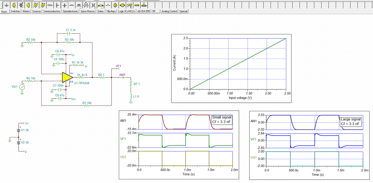
    Kai is correct, reducing the sense resistor value from 30 Ohms to 1 Ohm increases the overshoot and ringing. That is an indication that the phase margin has been degraded. Increasing the value of the feedback capacitor connected across the negative feedback resistor from 220 pF, to about 3.3 nF, reduces the overshoot and ringing by a substantial amount. The results can be seen in the TINA Spice simulation shown below.

    There may be other compensation methods that would result in an ever higher phase margin, but that analysis would require much additional time.

    Regards, Thomas

    Precision Amplifiers Applications Engineering

  • Hello, 

    I have ordered 2 EVM's thank you!

    really the last question. all the sims you showed me were of a square wave, what happens to sin wave?

    Alex.

  • Hi Alex,

    the sine is fine, precise and with very low distortion.

    Kai
  • Hello Alex,

    Regarding your questions:

    1. can I use the Improved Howland Current Pump Configuration Setup in order to answer my experiment needs.

    Yes, but you will need to use the OPA548 for the 1 Amp output current.

    2. the user guide has a BOM table, does everything in the BOM table is coming as a part of the package of the module?

    The EVM kit is kited to provide the items listed in Table 8, "Bill of Materials," that corresponds to the circuit shown in Figure 12, "Complete OPA547EVM, OPA548EVM Schematics." The listed components are installed on the EVM PC board. You will have to supply resistors and capacitors that are unique to you design. Also, keep in mind that the EVM kit comes with an OPA547, and you will need to obtain an OPA548 for your higher current application.

    Regards, Thomas
    Precision Amplifiers Applications Engineering