This thread has been locked.

If you have a related question, please click the "Ask a related question" button in the top right corner. The newly created question will be automatically linked to this question.

XTR115: The output issue for XTR115

Part Number: XTR115
Other Parts Discussed in Thread: XTR111

Hi team,

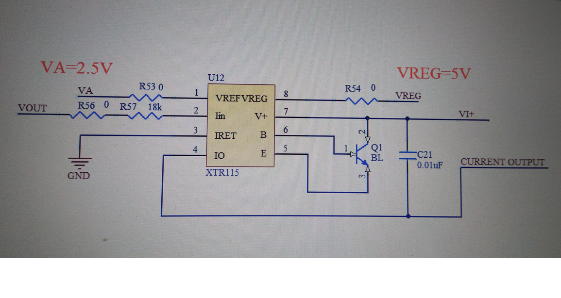
The customer uses XTR115. His schematic is in the attach. The input voltage is 0~3V. 

The output voltage for VREF is 2.5V all the time. The output voltage for VREG is 5V all the time. 

At the begin, the output current can meet IO=100*IIN. After a few minutes, the output current 

cannot meet this formula.

Then he change another new XTR115 device, then the output current canmeet this formula.

Q1. What the input range is for XTR115?  Can the 0~3V input voltage meet the input voltage range?

I note the datasheet shows "Common full-scale input voltages range from 1V and upward" on page 5. 

Is the input range from 0~1V?

Q2. Would you check if the customer's schematic correct?

Q3. For the customer's issue, would you provide some suggestions?

Best Wishes,
Mickey Zhang
Asia Customer Support Center
Texas Instruments

  • Hi Mickey,
    Our XTR expert is currently out of office, but looking at this circuit, I don't see any obvious issues. The input voltage range will depend on the value selected for R56 and R57. With an 18k input resistor, 3V at Vout becomes a 166µA input current, which would translate to a 16mA output current.

    What is the customer's output current range? Is this a standard 4-20mA output, or a different range? When output current is measured during correct operation versus the fault mode? If the customer swaps a faulty XTR115 back into the circuit, is the output correct for a short time still, or is the failure permanent?
  • It looks like the customer is trying to use this 2-Wire 4-20mA device in a 3-Wire application.  For 3-Wire application consider XTR111.

    See attached article that describes the difference between 2 and 3 Wire 4-20mA.  

    Planet Analog - Signal Chain Basics - The basics of 4-20mA current loop transmitters.pdf

     Also read this blog post:

  • Hi Tim,

    OK. Thanks for your help.

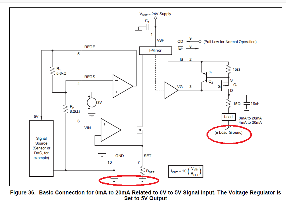
    Q1. If the customer uses 3-wire application, such as XTR111, I would like to get how to design the schematic. For the Figure 36 of XTR111, such as the attach, are the two red circles GND connected together?

    Q2. Is there any blog about 3-wire application, such as XTR111?

    Q3. Regarding the figure 3 of the attached article that you has sent to me, it shows "

    The 3-wire sensor transmitter topology (Figure 3) supports sensor transmitter designs that require >4 mA of
    operating current." Would you explain why the sensor transmitter designs can be higher that 4 mA?

  • Hi Mickey,

    For Q1: Yes the ground connections are intended to be the same because in a 3-wire design the general assumption is that you have a power supply local to your transmitter and thus run a ground wire out to your sensor. Depending on the wire length however, your sensor ground may be at a slightly different potential. As long as it is not significantly different and you remain within the compliance limitations of the XTR111 then there is no issue.

    Q2: The DAC group has a blog series about 3-wire industrial applications that you can find here: e2e.ti.com/.../industrial-dacs-an-overview-of-analog-outputs-and-architectures

    Q3: For 2-wire devices, all of the current consumed by the input circuitry is returned through IRET and becomes a part of your output current. Consequently in a 2-wire system you can't have an output current less than what your input circuitry consumes. In a 3-wire application, the input circuitry is referenced to ground and it's current consumption is unrelated to the output current, so you can consume as much current on the input stage as you need.
  • Hi Mickey

    We haven't heard back from you so we assume this resolved your issue. If not, post a reply below, or create a new thread if this one is timed-out.

    Thanks
    Dennis