This thread has been locked.

If you have a related question, please click the "Ask a related question" button in the top right corner. The newly created question will be automatically linked to this question.

TLV4376: Op amp Stability with increased output impedance and capacitive Load

Part Number: TLV4376
Other Parts Discussed in Thread: TLV376

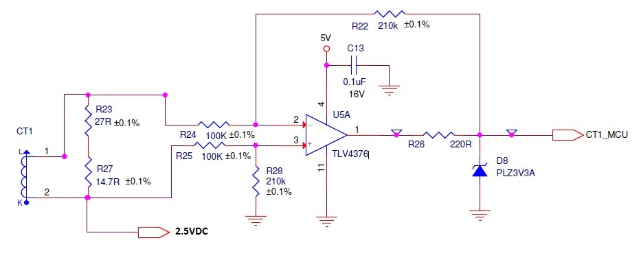
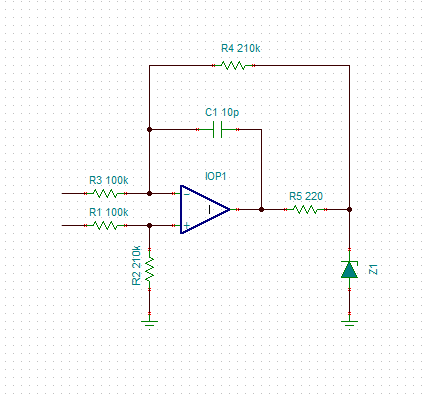
In schematic attached above, VCM=2.5. To get lower input offset voltage, V+ should be more than 3.5V as per section 7.3.4 of device datasheet. But, here the problem is, output is directly connected to ADC input pin of Microcontroller operating at 3.3VDD and 3.3VDDA. Hence we have added 220R and a zener to limit the output voltage. Feedback is taken after 220R to compensate the diode leakage current error.

1) Is 150 ohm output impedance of TLV4376 op amp is sufficient for current limiting in case of op amp output saturation due to some reasons?

2) Is there any stability issue here due to increased output impedance and capacitance of zener diode?

  • Hi Chethan,

    1) The 150 Ohm output impedance you are seeing in the table is only valid at higher frequencies once the device starts to run out of bandwidth. This parameter is actually the open loop output impedance of the amplifier, and it changes quite significantly over frequency as shown in figure 21 below.

    It will not limit the current in the manner you are looking for. Using a 220 Ohm resistor during a saturation condition you could expect roughly (5V-3.3V)/220 = 7.7mA of current to flow through the zener diode. 

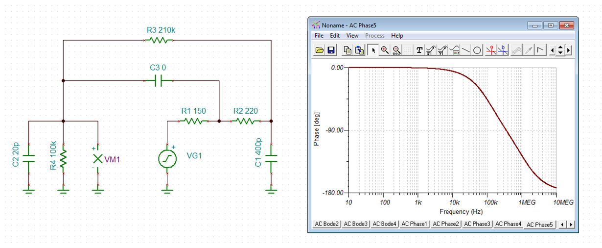
    2) From a stability perspective you are likely better off increasing the output impedance with the 220 Ohm resistor because of the reactive nature of the TLV4376 output impedance. This is because if the impedance of the total capacitance on your output intersects the output impedance of the TLV4376 in the region where it behaves inductively, it will create an LC resonance. Adding this resistor will make the output impedance look primarily resistive over most of the device's usable bandwidth, as shown in the simulation plot below:

    3) There is another area of concern in the schematic though. The large resistances you are using around the device are more likely to contribute to a stability issue, because they will interact with the relatively large input capacitance of the TLV376 and force your output to increase over frequency, which will degrade your phase margin. This could be fixed by adding a capacitor in parallel with your feedback resistor. Anything larger than ~6pF should do the trick. 

    4) Generally speaking, you will get better resolution out of your converter if you place an RC on the output of your amplifier. However you have to be careful to make sure this doesn't make the amplifier unstable. You may want to include footprints on your PCB for these components just in case, and evaluate whether you are satisfied with the performance without them present. The optimum values for these components is going to depend on the characteristics of your converter.  

  • Hi Chethan,

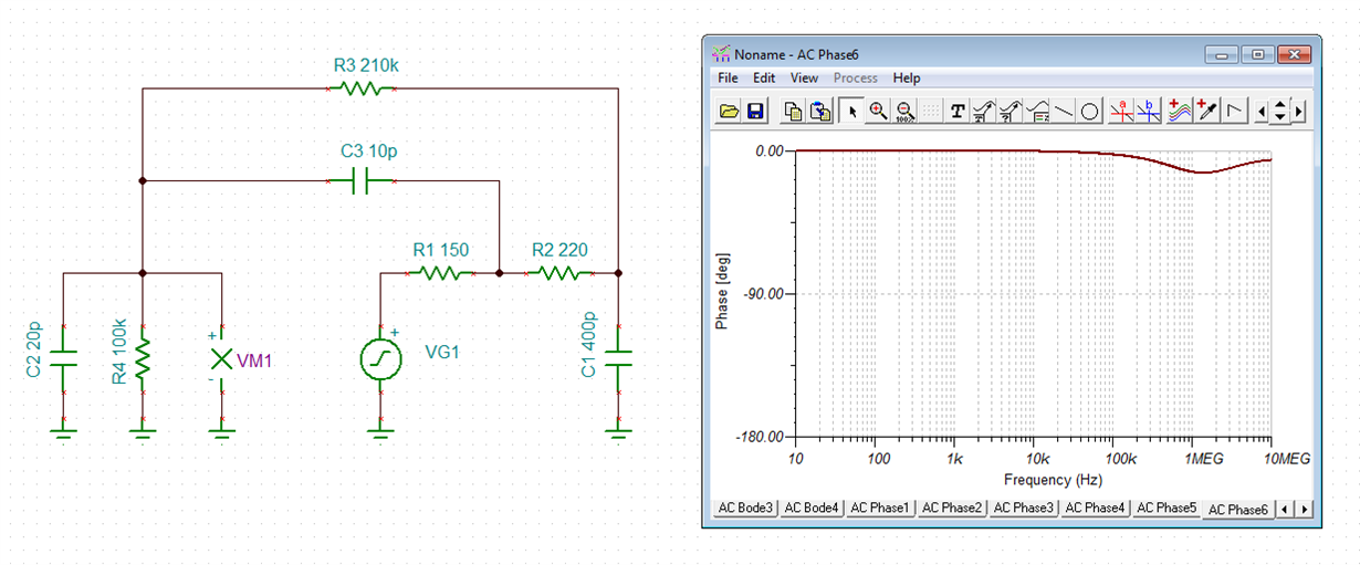
    Zak is fully right: You should add a small capacitance from output of OPAmp to -input of OPAmp. This would restore the eroded phase margin of OPAmp:

    Kai

  • Hello Zak Kaye,

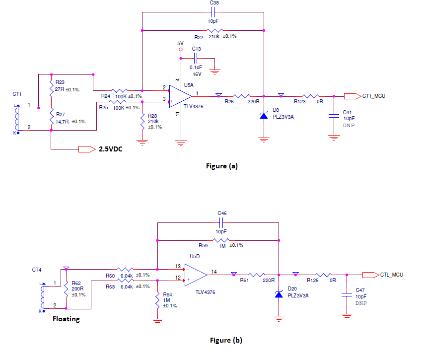
    Thank you for valuable inputs. I have added 10pF feedback capacitor and a RC filter option at the op amp output as shown in Figure (a) below.

    Since larger resistances around op amp is a area of concern, i have one more query. In the same application, we need to measure a 15mV signal and planning to use TLV4376 as shown in Figure (b) below.

    1) Considering op amp inputs as virtual short, CT output will see (6.04K+6.04K) in parallel with 200 ohm burden resistance. Is this assumption correct? Can i reduce 6.04K resistance to say less than 1K ohm without introducing any additional measurement error. So that feed back resistance required will also decrease.    

    2) Is there any other areas of concern in high gain amplification? Any modifications required for Figure (b).

    Input signal frequency is 60Hz AC.

    Thanks & Regards,

    Chethan K S

  • Hello Kai,

    Thank you for providing the simulation results. I assume 10pF feedback capacitor after 220R also will provide the same result.

    Thanks & Regards,
    Chethan K S
  • Hi Chethan,

    yes, will be sufficient. The stabilizing effect is a bit stronger if you connect the 10p cap directly to the output of OPAmp.

    Kai
  • Hi Chethan,

    A 10pF capacitor on the output of the op amp does not solve the stability problem like the 10pF cap across the feedback resistor does. Depending on the size of the capacitor, it can actually make the problem worse! With a cap across the feedback resistor you are shorting out the feedback resistor over frequency, which means the op amp's output can decrease over frequency. With a cap on the output you are shorting out the op amp output, which means it has to drive even harder to maintain feedback and this manifests as a degradation in Aol.

    Your assumption on the input impedance is correct, the differential input impedance is going to look like 12kOhms in parallel with your burden resistor. If you can't tolerate much deviation in value of your burden resistance then I would not recommend decreasing the resistor values. Adding the capacitor will solve your issue. To preserve your CMRR across frequency, it is also a good idea to add a capacitor of equal value across the resistor on the noninverting input, R64.

    As far as high gain concerns, you have to keep in mind that your offset voltage and noise are going to see the same gain and this may introduce significant error. High gain also makes it more difficult to achieve good settling performance into the converter. If you only need to pass a 60Hz signal I would recommend increasing the value of your feedback capacitor to throw away as much bandwidth as possible, as this will reduce your noise error and significantly improve your load transient response.
  • Hi Chethan,

    just noticed from Zak's last comments, that my last post could be misinterpreted. Of course, I didn't mean the 10p cap to be mounted from the output of circuit to ground, but from the output of OPAmp to the -input of OPamp, like I have shown it in my simulation. Just like this here:

    Kai

  • Hello Zak Kaye,

    Thanks for the valuable inputs. I will go ahead for the prototype.

    I added a resistor and capacitor option at the output of amplifier for a filtering purpose if required. As per your first reply Sl.No. 4 shown below.

    4) Generally speaking, you will get better resolution out of your converter if you place an RC on the output of your amplifier. However you have to be careful to make sure this doesn't make the amplifier unstable. You may want to include footprints on your PCB for these components just in case, and evaluate whether you are satisfied with the performance without them present. The optimum values for these components is going to depend on the characteristics of your converter.