This thread has been locked.

If you have a related question, please click the "Ask a related question" button in the top right corner. The newly created question will be automatically linked to this question.

TLV07: About TLV07 voltage follower

Part Number: TLV07
Other Parts Discussed in Thread: OP07, OPA202

Hi,

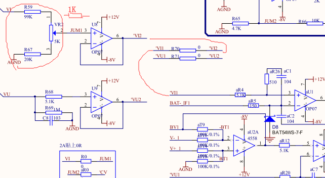
As the following figure.

U8(TLV07) is voltage follower, Positive input connected 1K  resistance, and input is DC 1V,  some device(about 10 pcs have been found so far.) output is issue, output is -7V, and changed other device output is OK, output is 1V.  U8 is OP07, We didn't see that(This board has been produced for many years, it used OP07).  Could you help me analyze it, thanks.


  • Hi Li,

    is the bug reproducible?

    Is the input voltage applied before U8 is powered-up?

    Can you increase the 1k resistor? Is it still happening then?

    What is the purpose of aU1?

    Kai

  • Li,
    I'm not sure how you came up with 1kohm equivalent input resistor but with V1 of 5V you should be able to adjust the input between 0.806V to 1.008V
    Therefore, I can think of two potential reasons for what you see: first, you have a poor connection across JUM1 (the input is floating) and thus the output collapses on its negative rail or the part has been damaged (e.g. ESD). Please verify the input voltage directly on pin 3 of U8.

  • Hi Li,

    One other quick note, if you are looking for a drop in upgrade for the OP07, then the OPA202 is a much better replacement as it is actually designed to be a performance upgrade for the OP07. The TLV07 is made on an entirely different process technology and has some characteristics that may not be compatible with existing OP07 designs. However, I do not believe this is the source of your issue and I would agree with Marek that you likely have poor connections or damaged parts.
  • Hi Kai,

    is the bug reproducible?

    Yes.

    Is the input voltage applied before U8 is powered-up?

    It's not related. It's the same thing.

    Can you increase the 1k resistor? Is it still happening then?

    Incresase to 5.1K, it is still happen, 1K changed to 0 ohm, it is ok.

    What is the purpose of aU1?

    U1 is constant current circuit.
  • Hi Mark,

    The resistor was changed 1K to 0 ohm, the device output is OK, I have tested again and verified the input voltage directly. Most of TLV07 work whether the resistor is 1k or 0 ohm, so far there have been few such device.
  • Please verify the input voltage directly on pin 3 of U8.
  • Li

    We haven't heard back from you so we assume you were able to resolve your issue. If not, post another reply below.

    Thanks
    Dennis
  • pin 3 of of U8 is -4V
  • Hi Li,

    Given that the issue goes away once you reduce the source impedance, I suspect this may be a flux contamination problem. Flux from the soldering process can create parasitic paths between pins and cause excessive dc errors, often making the bias current appear much larger than it really is. Are you properly cleaning these boards after assembly? Even boards that "look" clean can exhibit this behavior because the flux can get trapped underneath the part. If you have access to an ultrasonic cleaner, then this is one of the easiest ways to verify whether this is the problem.
  • Li

    We haven't heard back from you so we assume you were able to resolve your issue. If not, post another reply below.

    Thanks
    Dennis