This thread has been locked.

If you have a related question, please click the "Ask a related question" button in the top right corner. The newly created question will be automatically linked to this question.

OPA2192-Q1: Rail-to-rail input

Part Number: OPA2192-Q1

I plan to use OPA2192-Q1 op amp to scale down an input voltage using a simple inverting configuration (see figure below). The maximum input voltage I am expecting is 30V, such that the maximum output will be 30 * (-100/499) = -6.01V, which is within the rails. I have read up on rail-to-rail input/output, which mean that the input and output voltages cannot surpass the supply voltages, +15V and -15V. However, in an inverting op amp, the voltage of the inverting input is the same as the non-inverting input, which is a virtual ground. I am just confused about whether I can send an input voltage of 30V because the actual input to the op amp is a virtual ground, or is my input voltage of 30V limited by the supply voltages as well?

  • Hi Angela,

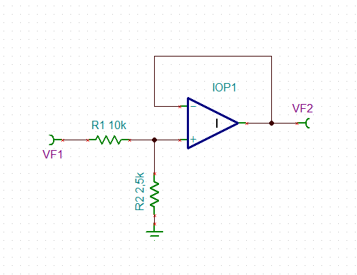
    why not doing it this way:

    Kai

  • Hi Kai,

    Thank you for your suggestion. Please confirm that my understanding of your circuit is correct:
    1. The equation of the op amp is given by Vout = 2.25*Vin/12.25, so that the gain is no longer inverted.
    2. Also, both the inverting and non-inverting inputs are limited to Vout, which is within the supply rail, so that my Vin can be any voltage under 15 * 12.25/2.25 = 81.7V? (as long as my Vout is within 15 V)

    I would also like to know why op amps typically use really large resistances? I would like to measure the Vout using an A/D so I would like it to be as accurate as possible. I thought using smaller resistances with a small tolerance (0.01%) would be better than using large resistances (since their error is greater). Could I still use the 100 and 499 ohm resistors or would that pose a problem? Thanks!
  • Hi Angela,

    Vout = 2.5k x Vin / 12.5k, if R1 = 10k and R2 = 2.5k. And yes, the gain is no longer inverted. And yes, up to 12.5k / 2.5k x 15V = 75V can be applied to the input.

    The feedback resistors of OPAmps are usually in the 1k...10k range (or even beyond) because the output stage of OPAmp must be able to sink and source the signal currents through the feedback resistors. In order to keep the distortion, the heat dissipation and the current consumption minimal, it makes sense to keep the feedback and load currents rather small.

    The maximum precision and minimum long term drift is usually found in resistor arround 10k, depending on the actual brand, of course. It's important to keep the resistor temperature under 40°C to achieve best long term drift. Again, higher resistor values can help to keep the heat dissipation low.

    Kai

  • Oops, I misread 2.5k to be 2.25k.
    I just made a simple calculation and it turns out that even with the maximum error with a 0.005% tolerance, the result is just as accurate as the low resistance values I wanted to use initially. Thanks so much for your recommendations; I will use them in my next PCB design :D

    P.S. how do I undo this resolved my issue? I misclicked and did them to my own posts..