This thread has been locked.

If you have a related question, please click the "Ask a related question" button in the top right corner. The newly created question will be automatically linked to this question.

OPA4277: Issue with applilcation comparing with OPA4171

Part Number: OPA4277
Other Parts Discussed in Thread: OPA4171, OPA2277

customer found the OPA4277 has something problem on Energy Storage system pls find the attached file.

When using OPA4171, the problem is gone. pls help to advice what parameter are importance on the design of the fre. buffer and over current protection. very thanks.

PVI OPA4277 Issue.pptx

  • Brian,

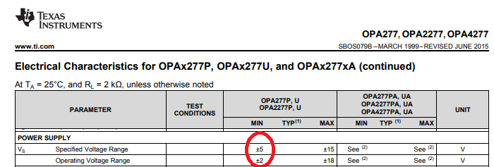
    3.3V single supply voltage violates the minimum supply voltage specified in the datasheet - see below.  OPA2277 requires a minimum operating supply voltage (datasheet limits do NOT apply) of 4V (+/-2V) while the minimum specified supply voltage is 10V (datasheet min/max limits apply).

  • Hi Brian,

    What are the V1 and -V1 supply levels used to power UM30A - UM30D, as seen in the Problem 1 slide? Since Vref is 1.65 V I suspect that they are low voltage as well.

    The waveforms on slide 4 show the differences in the circuit behavior with the OPA4171 and OPA4277. It is difficult to make out the details of the waveforms, but it is clear that there are additional spikes on the upper and lower waveforms when the OPA4277 is in the circuit. They may be due to a power supply violation issue like Marek observed for the Problem 2 circuit, or a input common-mode voltage (VCM) or output swing violation.

    Note that the OPA4277 VCM min is (V-) + 2 V, and VCM max is (V+) - 2 V. The OPA4171 VCM min is (V-) - 0.1 V, and VCM max (V+) - 2 V. There is a big difference on the minimum end between the two amplifiers. If the common-mode voltage in the circuit moves beyond the VCM range the normal operational amplifier behaviors can be severely degraded, or even lost.

    Regards, Thomas

    Precision Amplifiers Applications Engineering

  • Hi Marek :

    V1 is 12V and -V1 is -12V in th circuit

    Ho Huang
    Delta Electronic, Inc.
  • Hi Thomas :

    1.V1 is 12V and -V1 is -12V in th circuit
    2.Vs is +/- 12V,and IBTMAX max is 1.5V on slide 4. I don't think the common-mode voltage over the range. Or you can suggest us how to confirm it ? measure what pin voltage ?

    Ho Huang
    Delta Electronic, Inc.
  • Hi Ho,

    I have a question to "problem 2": You have OPA4171 voltage followers powered by +3.3V and fed the same voltage to the + input pins? Does this make any sense? And you have connected 2µ2 caps directly to the outputs of voltage followers? But connecting a high capacitance directly to the output of OPA4171 wired as voltage follower erodes the phase margin of OPAmp is very bad design practice. It also violates the recommendation given in section 8.2.2.1 of datasheet of OPA4171.

    Kai
  • Hi Ho,

    Is the inductor connection across the IBT_- and IBT_+ inputs of UM30A? Would it be possible to provide us the two DSO images on Pg. 4 as separate and larger images? It is very difficult to make out the details of the two small images in the report. We really need to be able to see what the waveform look like at the UM30A inputs and outputs more clearly.

    Since the IBT waveform traces are that of the inductor current (red) and IBTMAX (blue) output it appears that the questionable OPA4277 behavior is taking place in the UMA30A circuitry, and not elsewhere in the circuit. It almost appears as if the loop losses and then regains control, at a particular voltage point on the upward-going portion of the triangle wave.

    Regards, Thomas

    Precision Amplifiers Applications Engineering

  • Hi Ho,

    Has this issue been resolved satisfactorily? If so, please close out this E2E inquiry.

    Thank you, Thomas
    Precision Amplifiers Applications Engineering