This thread has been locked.

If you have a related question, please click the "Ask a related question" button in the top right corner. The newly created question will be automatically linked to this question.

INA125 design to use

Other Parts Discussed in Thread: INA125

Hi all,

FIrst of all I want to tel that my knowledge in this area is quite limited so please be gentle if I ask stupid questions :)

I work on a school project where I need to build a gauge with 4 load cells. I am using 4 x ina125P (one for each sensor) and read data using arduino and sent it to a database.

Now, this is what I have done :

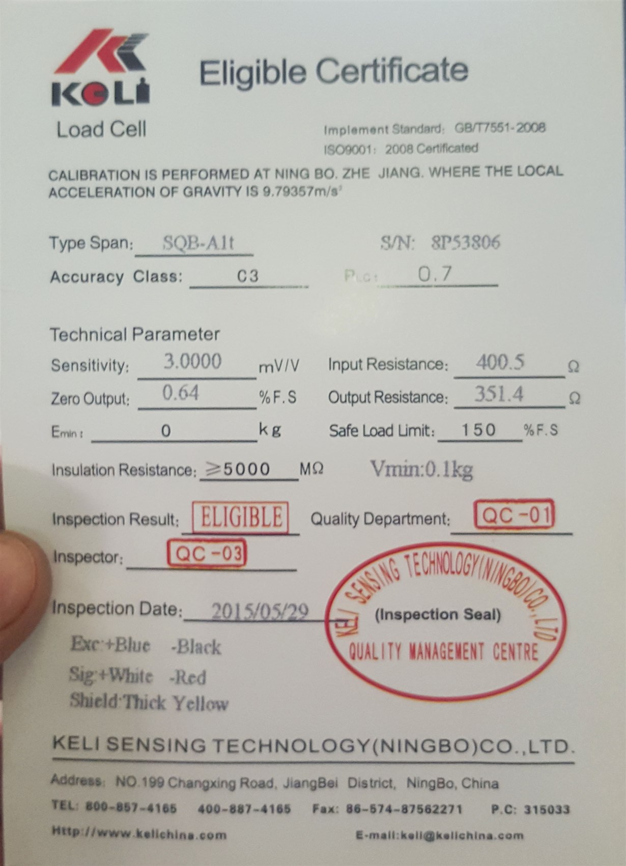
1 - This is load cell (I have 4 of them)

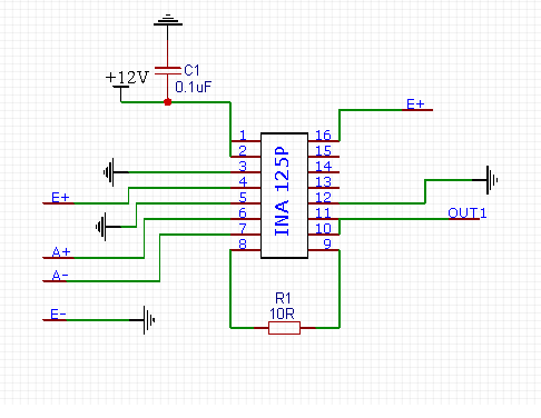
2 - this is how I am using ina  125 (I have 4 of this made on a test pcb)

So each ina is wired to one sensor. Now the questions:

1 - When I measure output of each ina, on 2 of them I have around 80-100mA and on 2 of them I have around 150-170 mA. Is that normal? The measurement is made when sensors are in repaus mode.

2 - I saw here on forum some schematics which use some transistors and also some resistors. Is the way that I am using ina the correct one or can you suggest me other schematic?

3 - Where I should wire the shield of the sensors? To the ground? 

Thank you very much .

Thank you very much in advance

  • Hi Lucian,

    10V across a 400R load cell means a current of 25mA. That's more than pin 4 of INA125 can deliver (<5mA). As a remedy you could use the method shown in figure 4 of datasheet.

    Kai
  • Hi,
    There is a mistake. I mean is about mV not mA.
  • Hi Lucian,

    Kai is not referring to your measured output, but to the supply of your load cell. The way you have it configured you are exciting your bridge with 10V. Since your bridge resistance is 400 Ohms, this is going to require 25mA from the INA regulator, which it is not capable of supplying. You can use the transistor trick as Kai has mentioned or add resistance at the top and bottom of your bridge to limit the current, though this will result in a lower voltage across the bridge resulting in less resolution.

    With a 10 Ohm gain setting resistor you are operating in a gain of 6004. This is a very large gain and is going to amplify noise in your system as well as offsets. With a maximum offset voltage of +/-250uV, you could expect up to +/- 1.501V and this would still be considered within guaranteed operation. I suspect what you are actually seeing is the output saturated at the negative rail, as it can only swing within 150mV (typ) of the negative supply.

    You are also using the device in single supply without a reference voltage, and this limits you to positive differential input signals.

    The shield wiring should not be critical in this application since your bridge is very low impedance, but generally speaking it is best to drive the shield to the same potential as your common-mode voltage to minimize the effects of currents due to parasitic capacitance between the shield and the signal line. For this application you should be fine to just ground the shield.
  • Hi,

    Now I understand what you mean. Thank you very much

  • Thank you very much for this explanation. I will reconfigure the setup using transistor and change gain resistor. Do you think 510R should be fine?
  • Hi,
    I did some tests and here are the results:
    I did 3 test circuits using 3 ina. First I also put a BC337 transistor, second and third without transistor. Gain resistor was 560 ohms on all 3 circuits. Sensor for testing was 2.5t (2mV/V).

    I - no load - output between 116.5mV and 117.3mV
    50kg = 3.1V
    100kg = 6.61V
    150kg=10.1V
    165kg=11.15V
    After this output is blocked at ~11.3V no matter what load to the sensor

    II - no load - output oscillating 230-290mV. After grounded the load cell shield get output relatively constant 194-205mV
    50kg=2.35V
    100kg=4.56V
    150kg=6.68V
    200kg=8.86V
    250kg=10.94V
    Again output freeze at 11.3V no matter the load is applied.

    III - no load - 126-134mV . After ground shield get 119-121mV
    50kg=1.76V
    100kg=3.66V
    150kg=5.5V
    200kg=7.37V
    250kg=9.33V
    300kg=11.18V
    Again output freeze at 11.3V no matter the load is applied.

    Are these values normal? I tend to believe they are not...
    Why always output is freezing on 11.3 V ?
    Thanks
  • Hi Lucian,

    if you supply the INA125 with 0V...12V, then the output of INA125 cannot fully go down to 0V or fully go up to 12V. This is quite normal and is called "output saturation".

    The gain resistor, is it really 560Ohm? Have you measured it? And do you have 10V across the load cell? Have you measured it?

    What is the sensitivity of the load cell? 2mV/V at full scale? And what is the full scale of the load cell?

    I would supply the INA125 with a bipolar supply voltage of +/-15V.

    Kai

  • Lucian

    We haven't heard back from you so we assume this resolved your issue. If not, post another reply below.

    Thanks
    Dennis