This thread has been locked.

If you have a related question, please click the "Ask a related question" button in the top right corner. The newly created question will be automatically linked to this question.

OPA189: How to measure input bias current

Part Number: OPA189
Other Parts Discussed in Thread: TINA-TI, LMC660

Hi all,
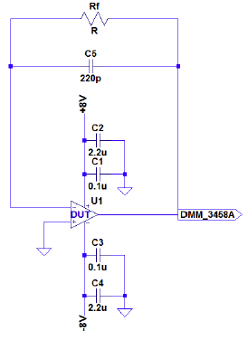
My customer tried to measure input bias current of OPA189 by below circuit.

In order to predict the offset voltage and Iib, they plotted the values of Rf as 0, 1 k, 10 k, 100 k and converted from the output and estimated the value of Iib, it was about 1000 pA.
I think it is necessary to consider extrinsic factors such as leakage current on PCB in the case of IIB of several 10pA like OPA189.

Do you have a recommended measurement circuit?

Regards,
Toshi

  • Toshi,

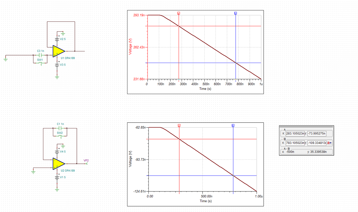
    The input bias current, IB, in CMOS op amp cannot be measured using resistor because of its tiny magnitude but instead must be integrated as shown below and calculated using Ic=C*dV/dt equation.  In the simulation below, this would result in Ic=1nF*slope=1e-9*35n/500n=70pA

    I have attached below Tina-TI schematic so may may do your own simulation.

    OPA189 IB measurement.TSC

  • Hello Toshi,

    To add to Marek's comments, the LMC660 datasheet (and several of the LMC60xx family datasheets)  has a blurb in the Applications Section about measuring the fA input bias currents using integration (page 11).

    The preferred way is to use the inverting integrating configuration (cap in the feedback path, S2 and C2 in the datasheet figure).

    The inverting integrator has a fixed common mode point, whereas the non-inverting (cap on the non-inverting input) will change the common mode as the capacitor charges up.

    This is not a big problem at mid-common mode, but as you approach within a volt of the rails, the bias current changes as the ESD diodes start to contribute. So you end up with an inflection in what should be a linear integration.

    The best way is to use a separate integrator to measure the current. This also allows "empty socket" measurements to subtract out fixture leakages.

    Waaaay back in 1993, Bob Pease wrote an EDN article on measuring fA input bias currents, "Whats all this Femtoamp stuff, Anyways", and the follow-on Teflon article. Unfortunately, the offical EDN site is messed-up and does not have the images.

    Below is an archive of the National Semi Pease site, which contains several of the "What's all this..." articles.

     https://www.ti.com/ww/en/bobpease/assets/www-national-com_rap.pdf

    The Femtoamp article is on page 45, and the Teflon article is on page 41. What was true back then is still true now - the principals still apply - just the packages have changed.

    And, yes, his Technician "Paul" was me...

  • Hi Toshi,

    another way to solve the problem is just to trust the datasheet specifications and to avoid this sophisticated measurement... :-)

    Kai