This thread has been locked.

If you have a related question, please click the "Ask a related question" button in the top right corner. The newly created question will be automatically linked to this question.

OPA197: OPA197IDBVT output giving -15V in field IC got damaged

Part Number: OPA197
Other Parts Discussed in Thread: TL084, , OP07C

Respected Sirs/Madams,

I am using OPA197IDBVT for my PT100 voltage calibration in my windmill stack.

Previously I am using TL084 it is working fine, In the new design, I have introduced OPA197IDBVT.

I have attached the circuit below.

Problem: On the field, It suddenly gave -15V output instead of my calibrated voltage, after replacing the IC the PCB started working fine. But because of so many PCBs out there on the field, I got trouble from the customer. Do you have any idea of the failures???


  • Hi Kaushik

    the 10n cap between pin3 and pin4 of OPA197 erodes the phase margin and can cause stability issues. I would remove it.

    Kai

  • Hi Kaishik,

    is the windmill stack application an outdoor application? Do you have any sort of surge protection at the input and output of OPA197?

    Kai
  • Hello Kaushik,

    I did a stability analysis of your OPA197 circuit and it appears to have sufficient phase margin and it should be stable. You could check the output of the OPA197 on your working boards with a DSO and 10x probe, and make sure that there isn't any oscillation present. Even if the OPA197 were oscillating that wouldn't necessarily result in damage to the device, but it is better to avoid that situation.

    There are high series resistances in series with both inputs so they should limit the input current to low levels should there be an unexpected input voltage event. That tends to point towards an electrical overstress (EOS) event at one of the OPA197 supply pins. EOS can damage an op amp, and if the output stage gets damaged the output can end up at one of the supply levels permanently.

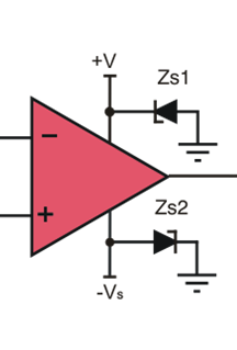
    One thing that we always recommend when the supply voltage characteristics haven't been fully characterized and may there is the possibility of an EOS event, is the inclusion of transient voltage suppressor diodes (TVS) from each supply pin to ground. You can see the way the diodes Zs1 and Zs2 are connected in the diagram provided below. The TVS diodes will turn on and clamp the supply voltage is a safe level should an EOS event occur. Since your application uses +/-15 V supplies the TVS diodes should have a reverse standoff voltage (VR) a little higher than the supply voltage.

    An added benefit of the added TVS diode to each supply is there is always a current path through the op amp through one of the diodes should one supply come up later than the other. This avoids latching issues that can sometimes occur with some op amps when the supplies do not come up at the same time.

    Regards, Thomas

    Precision Amplifiers Applications Engineering

  • Thank you, sir, noted, will update and check it accordingly. 

  • Respected Sir,

    I went through the faulty ICs.
    In that ICs, I found all clamping diodes which are there at the input side and an output side are OK. They were showing 0.5 diode drop.
    I have found Pin3 is showing negative voltage(around - 8V) instead of positive voltage.

    * I have done one experiment to simulate EOS. I have given 400V at input pin 3 for 4mS. Series resistor 10K is showing 40mA IN to pin 3.
    Although I got my circuit running fine. IC-197 has survived.

    Doubt: I have doubt on soldering pattern. Due to some reasons, we have soldered this ICs by manual solder instead of machine solder. Soldering temperature has been set around 320 ' C.

    Is there any possibility of damaging of this ICs due to manual solder ??? The package is SOT-23-5pin.
    Or any other reason?
    We have got failure after several days at the site.
  • Hi Kaushik,

    if you measure at pin1 of OPA197 the same voltage as at pin2 (-15V), then you probably have a short circuit from the manual soldering. Use an ohmmeter (DVM) to check this.

    Another cause for a high negative output voltage of OPA197 would be a short circuit in the PT100 cable!

    Usually, manual soldering does not destroy a SOT-23 chip, provided the soldering temperature and the soldering time are not too high.

    Kai
  • Hello Kaushik,

    You state:

    Doubt: I have doubt on soldering pattern. Due to some reasons, we have soldered this ICs by manual solder instead of machine solder. Soldering temperature has been set around 320 ' C.

    Is there any possibility of damaging of this ICs due to manual solder ??? The package is SOT-23-5pin.
    Or any other reason?

    So the OPA197IDBVT is being manually handled during the soldering operations - and it is the only IC being manually handled? If proper ESD handling procedures are not in place for manual handling, it is easy to damage an IC with electrostatic discharge (ESD). ESD can result in immediate failures, or latent failures. You need to check what ESD precautions are being used for all the handling operations associated with this manual soldering process.

    Regards, Thomas

    Precision Amplifiers Applications Engineering

  • Yes, sir, It is the only IC which was manually soldered. Other ICs were machine soldered.

    I got the latent failure because PCBs had passed all factory tests. It was running fine till several days from installation. 

    I will check out my soldering process. Will be back if having any doubts. Thanks for quick response. 

  • hello Kai,

    I have current limiting resistor 10K in series. If PT100 get shorted, Hardly 1mA will flow through the cable.
    In this case how my Opamp get damaged?
  • Hi Kaushik,

    not damaged, but a high negative voltage will appear at the output, if the PT100 wires are short circuited to each other.

    If this is an outdour application and you have the PT100 connected to the input via a long cable, then you will need a true surge protection at the input! Why not adding a unidirectional TVS to the input, in parallel to the 100n cap? Choose a TVS with low leakage current.

    And you will need the TVS at the supply pins, which Thomas recommended. If this is a real outdoor application, you circuit must withstand higher surges than 400V. Then the single 10k resistor will not help much. Add the TVS at the input and the TVS at the supply pins.

    Kai
  • Hello Kai,

    I will implement it and will send it to the field. 

    Yes, sir, this is an outdoor application. All PCBs are installed at remote locations. Cable length is around 300mm but the sensor is fixed on a heatsink, very near to the IGBTs. IGBTs are switched at 1200V DC. A  case of IGBTs is 2.5KV isolated from the heatsink. We have old boards based on OP07-SOIC8. More than 1000 PCBs are running fine at the field. We got the problem with the new design. My problem is any change I will do will take 2 months to verify whether the problem is solved or not. Will go with TVS, will be back thank you.


  • Hi Kaushik,

    aha! That's the killer! If there's enough stray capacitance between the IGBT and the heatsink and if the heatsink sits at a different potential compared to signal ground of OPA197 circuit, then dangerous equalizing currents can run into the OPA197 circuit and kill the OPA197!

    Kai

  • Hello Kaushik,

    I do find it interesting that the TL084 has been able to survive the killer events that Kai described. The TL084 has been around for about 4 decades and is fabricated on a bipolar process that includes the JFETs used for the input differential pair. The OPA197 is a new CMOS operational amplifier fabricated on a process where the transistor size is very small, and density is very high compared to an older bipolar process. Even though the two op amps perform similarly in your application they are very different in terms of the semiconductor processes they use. It appears in this case that the older technology is tolerant of the killer condition that may arise in the IGBT environment.

    Do let us know if the inclusion of the TVS diodes at the OPA197 power supply pins eliminates the damage happening with some of the devices.

    Regards, Thomas
    Precision Amplifiers Applications Engineering
  • Hi thomas,

    Sorry my mistake, actually I have the design with OP07C Which is running fine at field.
    Tl084 is used for temperature trip purpose as a comparator. Trip stage is comming after first OP07c stage.
  • Hello Kaushik,

    No problem. The OPA07C is a bipolar op amp from the early 1980s. My comments about its semiconductor process and transistor sizing, relative to the OPA197, apply to it as well.

    Regards, Thomas
    Precision Amplifiers Applications Engineering
  • Hi Kaushik,

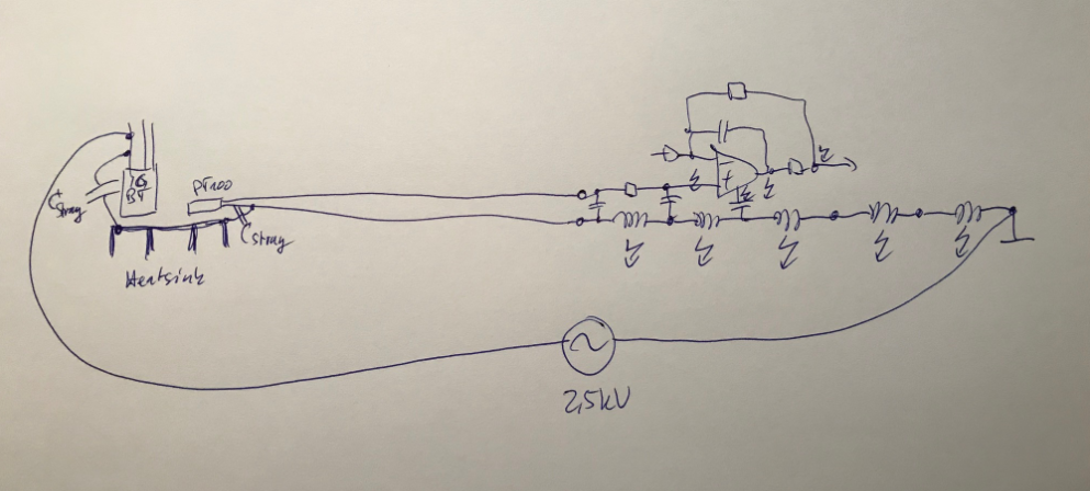
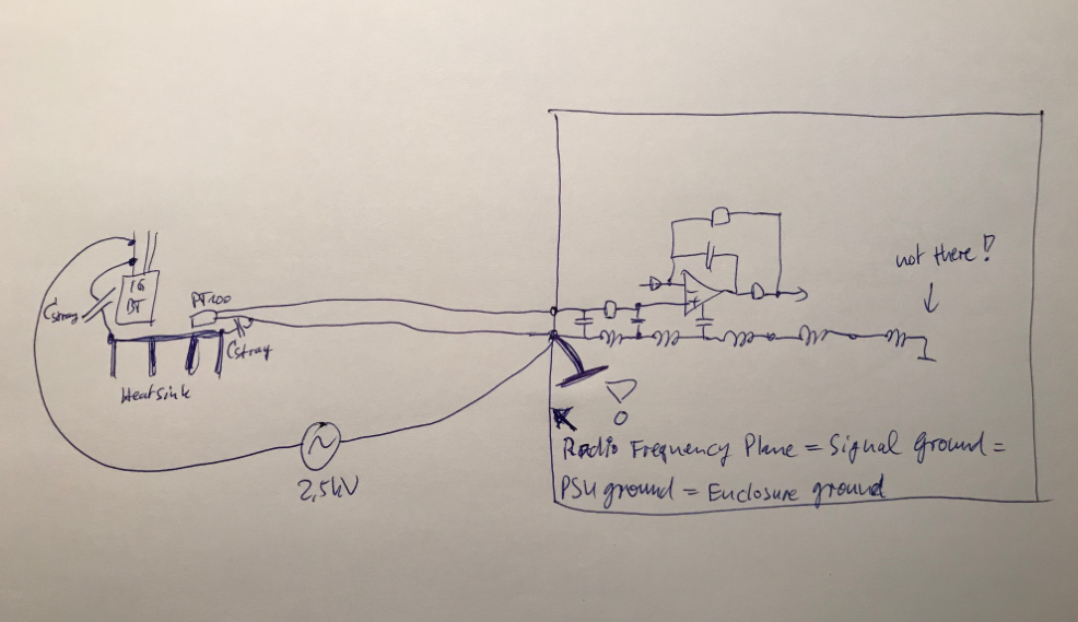
    the following two pictures shall show, how in your application dangerous currents can run into your OPA197 circuit:

    In the picture above the central star ground point is chosen on the far right. So, if there exists a AC potential difference between the 2.5kV IGBT voltage and this signal ground an equalizing current can flow from the 2.5kV IGBT voltage via stray capacitance to the heatsink, from the heatsink via direct connection or stray capacitance to the PT100 sensor, via the PT100 cable to the input of OPA197 circuit and finally via signal ground copper traces of PCB back to the central star ground point on the far right. If the signal ground copper traces show some inductance and if the 2.5kV IGBT voltage contains spiky voltage pulses, then dangerous potential differencies within the signal ground routing of PCB can develop. These can damage the OPAmp at every terminal, not only at the input terminal. That's why TVS can be helpful, not only at the input but also at the supply voltage pins, as Thomas already recommended. But also via the output pin a dangerous overvoltage can enter the OPA197. Only a PCB with a solid ground plane can minimize the inductance of the signal ground routing and by this the dangerous ground bouncing effects.

    But an even far better way to handle interference is to chose the central star ground point not on the far right, but at the place where the sensor signals enter (or leave!) the PCB:

    Cover the PCB with a metal enclosure and connect the signal grounds and power supply grounds to the metal enclosure right at the point where the cables enter or leave the enclosure. If you use shielded cables connect the shields also to this point. By this method interference can no longer cause any dangerous currents to enter the OPAmp circuitry. Interference currents will only flow anymore on the solid metal enclosure or from shield to shield, but will no longer enter the metal enclosure or flow across the PCB. When doing it right, the metal enclosure forms a radio frequency plane and massively profits from the skin effect. This method is also the best cure against ESD...

    Kai

  • Kaushik

    We haven't heard back from you so we assume you were able to resolve your issue. If you need more help just post another reply below.

    Thanks
    Dennis
  • Sirs,

    Yesterday I got the report from site persons. Out of 12 boards, 4 boards are faulty after one week of running at the site. Same problem Output of 197 sits on -15V permanently.
    In last modification, I have soldered smbj13ca across 0.1uF cap on pin3.
  • Hello Kaushik,

    It certainly sounds like an unexpected high voltage level (EOS) is being developed within the system and is being applied to the OPA197 in some manner. Damage to an input, an internal circuit on a supply line, or to the output could result in the output getting stuck at -15 V.

    Normally, when this kind of damage is occurring in a system we recommend equipping the various device pins with 10x probes to DSO inputs, and then monitoring them as the system is exercised through all its cycles. That often reveals an EOS that wasn't known. I am not sure that can be accommodated in your system.

    Have you tried adding the transient voltage suppressor (TVS) diodes to the supply pins on any of the boards having the OPA197?

    Regards, Thomas
  • Where does OP signal (pin 1 of op amp) go to? cable and another PCB or an ADC local on the same PCB?