This thread has been locked.

If you have a related question, please click the "Ask a related question" button in the top right corner. The newly created question will be automatically linked to this question.

OPA2541SM impedance inconsistency

Other Parts Discussed in Thread: OPA2541

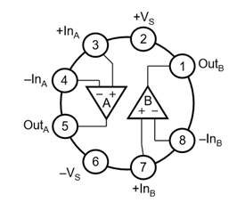
Using a multimeter on Pin 1 and 2 of OPA2541SM, the table below shows results on 3 separate units

Test Condition 1

Test Condition 2

Test  Condition 3

Test Condition 4

6(-Vs)

6(-Vs)

2(+Vs)

2(+Vs)

1(OutB)

5(OutA)

1(OutB)

5(OutA)

Pin Impedance value (?)

200Kohm ↑

200Kohm ↑

1.2Mohm ↑

1.2Mohm ↑

Unit 1

321K

319K

1.47M

1.51M

Unit 2

290k

217k

1.39M

1.25M

Unit 3

301K

310K

19.5K

1.4M

I'm not sure what the "Pin Impedance value" is.

Is there an explanation for the discrepancy for Unit 3, Test Condition 3?

A value of ~1.4Mohm is expected , but the result is 19.5kohm. Out of 100 pcs, 2 units had these discrepant results.

Is it simply a faulty unit, or could there be another explanation?

Any help would be greatly appreciated...

Thank you

  • Hi Mark,

    We do not characterize the pin-to-pin resistance of our PA op amps because instead we elect to measure the electrical performance of them under actual powered conditions, as they are used. That is certainly of more importance than the resistance between pins of an unpowered op amp which is often inconsistent between devices and can vary greatly between different production runs of the op amp.

    Here are the issues with resistance measurments:

    • The measurment value will vary by DMM depending on the reference current that the meter uses for the resistance measurement.
    • The measurment value often will vary due the polarity of the meter leads. Reversing the leads often produces very different resistances.
    • Production process variances will affect the resistance. Very different resistances may be measured between devices produced at different production times.

    Here is an example of the difference in pin 1-to-pin 2 resistance measured for a random OPA2541. A different DMM was used and the leads were reversed:

    DMM type            DMM Polarity          Resistance

                                Pin 2      Pin 1    

    HP34401A           ( + )        ( - )            2.62 Meg

                                 ( - )        ( + )            41.6 k

    Fluke 79 III           ( + )       ( - )             38.4 Meg

                                 ( - )        ( + )            3.03 Meg

    As you can see the results are very different for each situation.

    What is actually occuring the the above measurments is the internal ESD diode between the OPA2541 pins 1 and 2 is first reverse biased, and then when the leads are switched, forward biased. The two DMMs use different reference current levels and that results in different resistances due to the forward and reverse characteristics of the diode. If you are concerned about the 19.5 k measurment, try reversing your DMM's leads. If you find it doesn't change then there may be the possibility that the diode has been damaged. That usually from an ESD event incurred by improper handling.

    Keep in mind what is really important is that the OPA2541 meets its electrical specifications when the circuit is in operation. Don't be too concerned about the resistance unless there is a short (0 Ohms) between pins where there shouldn't be a short.

    Regards, Thomas

    PA - Linear Applications Engineering

  • Excellent. Thank you for your very thorough response. I will advise our QC team to reverse the leads and see what results.