This thread has been locked.

If you have a related question, please click the "Ask a related question" button in the top right corner. The newly created question will be automatically linked to this question.

Connect a Piezoelectric sensor to TLV2772 opamp

Other Parts Discussed in Thread: TLV2772

Dear All,

I am writing to you because I need your advice please. I would like to connect a piezoelectric sensor that may experience +-90V at high impact to the ADC of a microcontroller. Could you please let me know if the tlv2772 is suitable for such high voltages in order to constraint the output with the rail-to-rail voltages within 0-5V range? Or I should probably use 1MOhm resistor with a zener diode in parallel to the piezoelectric sensor and before  the tlv2772?

Thanks in advance and I am looking forward to hearing from you.

Best regards

George

  • Hi George,

    The TLV2772 is a low-voltage CMOS op amp and I do not recommend subjecting its inputs to the possibility of a high-voltage event. Any internal input clamping is intended to handle out-of-circuit ESD events, and not for for high-voltage EOS events. It would very likely be damaged by a high-voltage event.

    Adding a high-value series resistance after the high-voltage sensor, follower by a zener diode or transient voltage suppressor (TVS) to ground (right at the op amp input), is a good method to protect the TLV2772 input. Try to select a zener voltage that is close to the limit of the TLV2772 input range. Do be aware that such diodes do have high leakage current that will far exceed the input current of the op amp. Try and find a low-leakage zener, or TVS, to minimize the current load to the sensor.

    Also, be aware that the diode adds capacitance to the circuit whre it is connected. This can be an issue if that connection point is the op amp's summing node. That can reduce the phase margin and might compromize stability. If you want to send us a sketch of your circuit, we can look it over for any potential issues.

    Regards, Thomas

    PA - Linear Applications Engineering

  • Hello Thomas,

    I would like to thank you very much for your quick reply and advice.

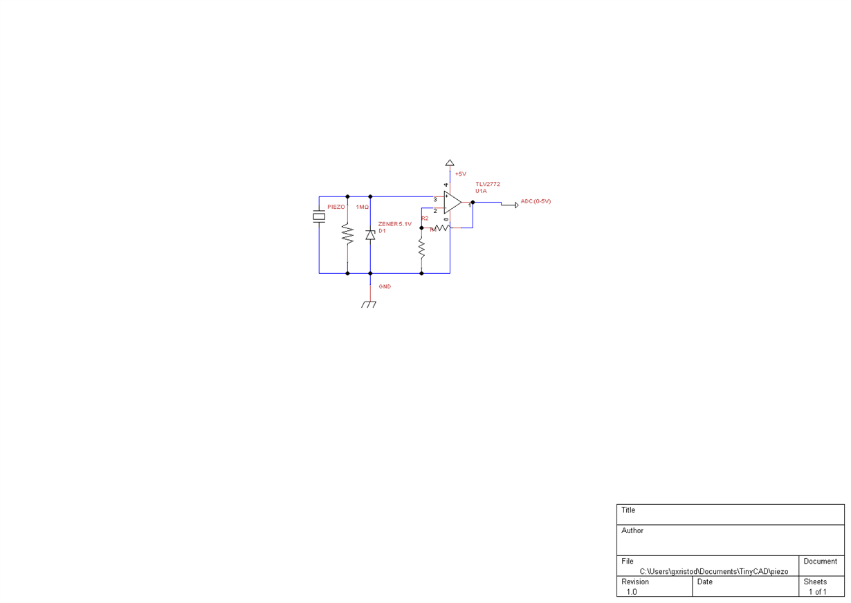
    The circuit I am thinking to build is shown below and the piezo I will use is the following .... dlnmh9ip6v2uc.cloudfront.net/.../LDT_Series.pdf

    In case the signal is too low to be readable I am intending to amplify it with the combination of R1 & R2.

    In case you see any potential issues at the schematic below advice me please.

    Best regards

    George

  • Hello George,

    It looks like your schematic is not displaying properly. If you copy and paste the picture into the reply box, the image will not render correctly. The picture below shows the "Insert/Edit Media" and "Insert File" options after clicking the reply button and then the "Use Rich Formatting" hyperlink. This will allow you to post your schematic. Sorry for the inconvenience.

    Best,

    -Cole

  • Hello Cole,

    Thank you very much for letting me know.

    The related schematic is attached.

    Best,

    George

  • Hello George,

    Thank you for the circuit schematic; it is helpful. 

    If the piezo sensor has limited output current capability and the zener diode is able to handle the maximum current that it can produce, then it shouldn't be necessary to include the series resistor I referred to in my earlier message. Indeed you do want to include the 1-Megohm shunt resistor because it provides a path for the TLV2772 input bias current and also acts as a load for the sensor output.

    Do study the 5.1 V zener specifications and make sure that it remains off over the required input operating voltage range. Also, do keep in mind the zener voltage tolerance.

    Since you are using the TLV2772 as a non-inverting amplifier you shouldn't have the stability concern I previously mentioned.

    Regards, Thomas

    PA - Linear Applications Engineering

  • Hello Thomas,

    Thank you very much for your quick reply and the valuable advice!!!

    Best,

    George