This thread has been locked.

If you have a related question, please click the "Ask a related question" button in the top right corner. The newly created question will be automatically linked to this question.

PGA450-Q1 EVM Problems

Other Parts Discussed in Thread: PGA450-Q1, PGA450Q1EVM

Hello

We are working on PGA450-Q1 EVM with 58 KHz transducer and TI GER interface Board and facing some issues.

Setup details:

We have configured all jumpers as per default setting (see Section 6.2 of user manual) and populated the R2 with 0 ohm resistance. Also we have the “PGA450 Customer GUI v1.38.32”.

As per the user manual, we start the Evaluation through SPI communication (using TI GER board).

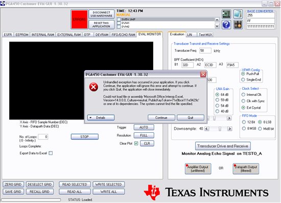
  1. In ESFR tab, we click the "OFF (Micro Reset)" button to put the Micro in reset, and then click READ ALL to read the default register values. Some default values are loaded in the table grid. After that, we fill the "Evaluation" tab with the values shown in Figure 10 of user manual. Then using the "Eval Monitor" tab, we press the “Transducer Drive and Receive” button and then the “START” button which leads to the following Error as shown in below image:
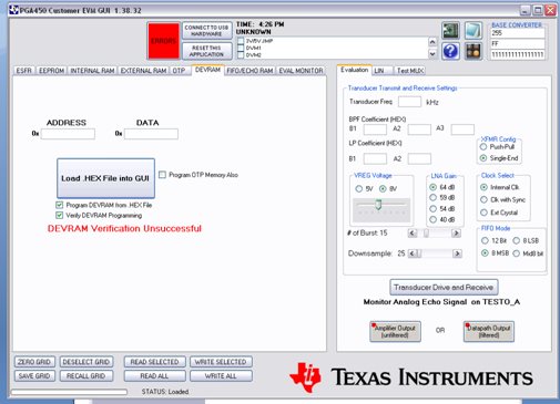
  2. When we are trying to Load the hex file through DEVRAM, we check the “program DEVRAM from .HEX File” and “verify DEVRAM Programming” boxes and load the hex file. Then we are get following Error as shown in below screen shot (we can also check on both conditions of check or uncheck the “Program OTP Memory Also” box):
  3. How to calculate the distance in feet or meter?
  4. How to configure the UART to send the distance information? If we require any programming to configure the UART, please provide all the necessary information.
  • Hello Praveen,

    i have contacted the supporting apps engineer and they will get back to you once an answer is available. Please note that the apps engineer is out on business travel this week and that responses may be delayed.

    Thanks and Best Regards,

    Wen-Shin Wang

  • Praveen,

    1. Please try using the attached GUI where we fixed a bug for Office 2007 users.  Let me know if this does not fix the problem.

    2. On your second screenshot, if you look at the top of the GUI there is a button called "Connect to USB Hardware", and below the time you can see, "Unknown".  Both of these items indicate that you are not actually connected to the TI-GER board.  To fix this, try reinserting the USB cable, cycling power on the PGA450, and restarting the GUI.

    If you are connected properly, the button will say, "Disconnect USB Hardware", and below the time will say, "Manual" (both of which appear on your first screenshot).

    3.  The distance can be calculated with the following formula:

    TOF (Time of Flight) = t_blanking + Location_FIFO * Downsample * t_sample

    Distance = TOF * v_sound/2

    The default for the blanking timer is 0, t_sample = 1us, and v_sound (room temp) = 343 m/s.  The downsampling rate is whatever number you select on the GUI, usually between 25 to 50. 

    4.   I don't currently have sample code for communicating to the PGA450 over UART.  The relevant information should be in the programmer's guide I sent you.  The two SFR registers of interest are the UART Control register (SCON) and the UART Data register (SBUF).  Look on pages 8-9 of the programmer's guide.

    PGA450 GUI 1.38.33.zip
  • Dear Clancy,

    Thanks for your support.

    Now PGA450 “GUI version 33” is working fine. But we are facing problem in TOF.

    We download the hex file in PGA450 and start communication on LIN as per “EVM Demonstration using PGA Firmware Rev 2.1” Document. But we are getting same response(in both Long and short distance setting) even we can change the distance between transducer and object. Also the FIFO data is same on every LIN query. Then we can check the Burst signal (at the time of LIN communication) in OUTA and OUTB using Oscilloscope, but we are not getting anything in those pins.

    Please tell us,

    Thank you

    Praveeen

  • Praveen,

    What TOF is being reported repeatedly?  What is the value repeated in the FIFO data?  Have you double checked that all of the jumpers are correct?

    Thanks,

    -Clancy

  • Dear Clancy

     Thanks for your support.

    For Long distance TOF: 1550

    For Short distance TOF: 0378

    Jumper Setting:

    VPWR:VOTP       Close

    VPWR:VLIN        Close

    JP4                         Close

    JP5                         Open

    JP3                         Close

    R2                           0 ohm resistance installed

     We are using LIN tab and start communication as per “EVM Demonstration using PGA 450 Firmware Rev 2.1” document. Steps which we are following:

    1. Load the Hex file in PGA450.
    2. Release the micro out of reset.
    3. Check the LIN communication, by clicking the RECEIVE button with PID 21 and data byte 2. In result, we have received 1234.
    4. We program the EEPROM through LIN TRANSMIT as per threshold valve: DC, 68, 59, 44, 33, 22, 11. Also we have checked these valves in EEPROM at location address 00 to 06.
    5. Now, we transmit PID 11 and data 0 for short distance measurement and Data Receive using PID 22 and byte 2.
    6. We are repeating step 5 many times with different-different Object distances. But we are getting same result (distance = 0.15 meter) in the GUI. Also we have saved the FIFO data every time, which we can share with you through email.
    7. Same steps for the Long distance to change the data 1 with PID 11 transmit and we are getting same result each time.(distance= 0.94 meter)

     Clancy-please check the FIFO data. Also confirm the firmware which we are using is the latest one.


    Thanks & Regards,5481.PGA450 - Firmware Rev 2.1.zip

    Praveen

  • Praveen,

    Does the FIFO read "FF" in all 768 bytes?  If not, will you please send me the excel files of the FIFO data for some of your short and long distance runs?

    What do you have programmed in the EEPROM?

    -Clancy

  • Clancy,

    We are waiting for your response.

    Regards,

    Praveen

  • Praveen,

    It looks like some noise might be getting injected into the system.  One common source of this is the power supply that you use.  Try using a battery to power the PGA450 and run your laptop off of its battery and see if your waveforms look cleaner. 

    Use this procedure to put the PGA450 in listen only mode:

    1. Load Rev 2.1 firmware
    1. Put the micro out of reset and send one long distance pulse
    1. Put the micro back in reset
    2. Write 0x01 to register 0xC3 (PWR_MODE)
    3. Write 0x00 to register C8 (EN_CTRL)
    4. Write 0x0C to register C8 (EN_CTRL)
    5. Read and Save FIFO data to file


    This will allow you to fill the FIFO without transmitting a burst first.  It is a great way to see the noise in your system.  For a long distance measurement, your noise should be below 10.


    It also looks like the decay time could be improved.  Please follow the attached procedure to improve the decay time.


    Once you've followed these steps and have a clean waveform, you can use the attached spreadsheet to help tune your thresholds.  Copy and paste your FIFO data into it, and then you can tune the threshold values to remove false detects.

    PGA450 tuning docs.zip
  • Dear Clancy,

    Thanks for your valuable support.

    I did it.

    For design, we require the transformer specification and vendor details.

    Also if possible, please arrange some transformer samples for our prototype design.

    Regards,

    Praveen

  • Dear Clancy,

    We are waiting for you reply.

  • I have the graph like below in EVAL MONITOR mode and setting as showing.

    But when I download PGA450_EVM.hex into DEVRAM and set it work as your description,it just get the correct distance serveral times,most of replay is 0.94m.

  • Praveen,

    I'm confused by your question.  Are you saying that when you download the hex file and invoke the distance measurement through LIN, you get the correct distance measurement?

    Note that the settings you have in the "Evaluation" tab do not completely match the example firmware.  To match the settings for a long distance measurement, change the number of bursts to 18 and the FIFO mode to 8 LSB.

    Would you please post an excel file with your results from the "listen only mode" test? (I posted the instructions for this in one of my earlier posts on this thread)

    -Clancy

  • same issue for me also , am getting the "FF" value from the FIFO in this stage , what do to now ?
  • Vinoth,

    Can you explain your issue in more detail?  Is the FIFO completely filled with "FF"?

    Thanks,

    -Clancy

  • Clancy,

                Thank you for your support. we are getting same repeating result (short distance = 0.15 meter, long distance= 0.94 meter) in the GUI.

    I seen the same issue faced some one and the solution also you given for that . so now am following that.

    My doubt is PGA450Q1EVM_Tuning_Procedure v2.pdf document says that , while programming to DEVRAM the  “Program OTP Memory Also” box is checked
    .if we do this method the OTP memory can we able to reprogram again ?  because in the datasheet about OTP memory re-programmed using UV-light
    EPROM eraser only.

    So if i want to modify the firmware and re-program means,  how to do ?

  • hello clancy ,
    what do you mean by location_FIFO, i mean how can i find it? can you please email me at ay.slimani@live.fr?
    thank you!

    Best regards,
    Ayoub Slimani
    INOZY, SAS Montpellier, France
  • Ayoub,
    location_FIFO is the location in memory of the FIFO RAM that a peak is detected. In the plot earlier in this thread by kaihua Zhang, there is a peak around point 310. So 310 would be the location_FIFO.
  • Hi Clancy,


    Thanks for your support.


    1-You said that "location_FIFO is the location in memory of the FIFO RAM that a peak is detected"...There are a lot of values which changed in the FIFO RAM , how can I know the correct value of the peak?!
    2-Do we have to calculate the value of TOF or we can find this value on the GUI?
    3-If we can find it on the GUI ,where exactly?

    can you please  email me at ay.slimani@live.fr ?  thank you!

    regards
    Slimani Ayoub

    INOZY SAS

  • Hi Clancy,

    How we can enter the threshold and where?

    thank you !

  • Dear Clancy,

    We are waiting for you reply.

  • Slimani,

    I e-mailed you some instructions for using the PGA450 firmware that talk about using thresholds.  Hopefully this clears up your questions.  After taking a look at it, please post on here what questions you still have.

    Thanks,

    -Clancy

  • Clancy,

    thank you for your support.

    I used this threshold level ( 0xDF,0x 6F,0x5F,0x 4F,0x 3F,0x 2F,0x 1F) and now I can detect up to 56 cm and no less but for our applications we need to detect less than 56cm.

    1-How to calculate/determine the EE-DATA values?

    2-Are they dependent on the material/environment that we measure ?

    best regards

  • Clancy,

    We are waiting for you reply.

    thank you

  • Hello Ayoub,

    Thresholds levels for long distance range can be set up independent to the threshold levels for the short distance range. The upper nibble of EE_DATA<0:6> controls the threshold levels for the long distance instruction, while the lower nibble of EE_DATA<0:6> controls the threshold levels for the short distance instruction. For short distance instruction, FIFO_CTRL (= 0x07) is set up for Mid-8bit mode with NO ROLLOVER in the firmware. For long distance instruction, FIFO_CTRL (= 0x06) is configured for LSB mode with NO ROLLOVER in the firmware.

    The preferred method of determining the threshold levels is to observe the FIFO DATA for a test set-up with no object (“empty set up”), and then define the appropriate levels. The raw FIFO DATA can be viewed by placing the micro in reset and clicking on the PGA450Q1EVM GUI's “Read and save FIFO data to file” button.

    To define/calculate EE-DATA values, see the relation between FIFO DATA location and threshold value listed in Table 1. For instance, at the short distance FIFO DATA location range between 0-3, the threshold is at (0xC)*16+4=196 when using TI's EE_DATA_<0:6> default setup of 0x(DC), 0x(6B), 0x(59), 0x(44), 0x(33), 0x(22) and 0x(11). You should be able to optimize for detection of less than 56cm.

    The environment will make an impact on the "empty setup" levels considering unanticipated reflections, external sources of noise, and temperature are examples of environmental factors. You need to define the thresholds to account for the worst case environmental conditions the transducer would be exposed to. Materials that absorb  rather than reflect may not register beyond threshold. You can also programmatically adjust the threshold to account for various environments/materials.

    Table 1. FIFO DATA Location of Threshold Ranges

    FIFO DATA location

    Threshold level for long distance


    Start

    End

    0

    31

    Ignore echo

    32

    63

    EE_DATA_0<7:4> X 8 + 12

    64

    95

    EE_DATA_1<7:4> X 8 + 12

    96

    127

    EE_DATA_2<7:4> X 8 + 12

    128

    159

    EE_DATA_3<7:4> X 8 + 12

    160

    191

    EE_DATA_4<7:4> X 8 + 12

    192

    223

    EE_DATA_5<7:4> X 8 + 12

    224

    255

    EE_DATA_6<7:4> X 8 + 12

    256

    767

    10


    FIFO DATA location

    Threshold level for short distance


    Start

    End

    0

    3

    EE_DATA_0<3:0> X 16 + 4

    4

    7

    EE_DATA_1<3:0> X 16 + 4

    8

    11

    EE_DATA_2<3:0> X 16 + 4

    12

    15

    EE_DATA_3<3:0> X 16 + 4

    16

    19

    EE_DATA_4<3:0> X 16 + 4

    20

    23

    EE_DATA_5<3:0> X 16 + 4

    24

    63

    EE_DATA_6<3:0> X 16 + 4

    64

    767

    4

  • Hello Ayoub,
    See our new "PGA450Q1EVM - Part 2. Using the GUI" video tutorial at:
    http://bcove.me/spb6ckwm
    This video includes an explanation on how and where to enter the thresholds in PGA450-Q1 EEPROM.

    Additional tutorial videos can be found under the "Videos" tab at:
    www.ti.com/.../support