This thread has been locked.

If you have a related question, please click the "Ask a related question" button in the top right corner. The newly created question will be automatically linked to this question.

PGA450-Q1 LIN Technical support

Other Parts Discussed in Thread: PGA450-Q1, PGA450Q1EVM, TIDA-00151

Hi,

I am using PGA450 for reverse distance sensing purpose in our automotive product.

I have PGA450-Q1 Evaluation board with me. it is communicated via pc GUI with LIN communication using following commands -

1.  PID = 0x21

2. PID= 0x11; data = 0x00

3. PID = 0x22; receive databytes = 2;

This is the communication between PC GUI to single slave on EVM.

My Question -

For our application, we are using 4 sensor for reverse distance measurement, i have question that, How to send LIN commands (like mentioned above) to particular slave out of the four?

How to communicate with individual slave using LIN frames?

Please reply soon.

  • Switesh,

    To communicate with 4 PGA450s, you can separate the 6 bit PID field into an device ID and a command.

    For example: PID field = NNNxxx

    NNN = ID number

    xxx = command

    (this structure works with up to 8 slave devices, you can adjust the bits accordingly to suit your system.  For a four node system, you could do NNxxx)

    You can still use the data field to further define your commands.  An example set of commands is:

    0 = start distance measurement

    Data field: 0 = short distance, 1 = long distance

    1 = receive distance

    2 = test

    Should return 1234

    3 = write first 7 bytes of EEPROM for echo thresholds

    data field should have 7 bytes of data.

  • Hi Clancy,

     Thanks for your accurate reply.

    Can you please provide any document for this.

    I am having Visio-PGA450 Location Identification.pdf document from that i can get the ID numbers for four slaves.

    Slave_1 = 0x00  // GPIO2=open; GPIO1 = open.

    Slave_2 = 0x01  // GPIO2=open; GPIO1 = Ground.

    Slave_3 = 0x02  // GPIO2=Ground GPIO1 = open.

    Slave_3 = 0x03  // GPIO2=Ground; GPIO1 = Ground.

    Then Can you please explain what are the LIN command set (PID) for these slaves?

    for

    1) test LIN communication (like 0x21, receive Databytes = 2).

    2) Start of measurement (Like PID = 0x11 ; Databyte 0x00 for short dist. measurement).

    3) Receive distance (like 0x22; receive databytes = 2).

  • Would you send me a copy of Visio-PGA450 Location Identification.pdf file?  I have also the same issue to identify the location of individual sensor module in parking assistant system.   Is there any other way to assign slave ID other than utilizing GPIOs electrical connection?  For smart parking assistance system or blind spot detection, we are going to use up to 12 sensors and I would like to have a solution which can be implemented in software via LIN master. 

  • 8306.Visio-PGA450 Location Identification.pdf

    Please see attached pdf. 

    With this doc only four slaves can be identified.

    i am also having doubt, how to identify 8 or 12 slaves?

  • Thanks for the file.  Looking forwards to a good solution.

  • There are a couple of options if your system has more than four nodes.  I've attached a document with illustrations for two ways to do this. 

    1. Daisy chain the LIN bus by using a GPIO and a switch to connect the LIN bus after receiving an address from the master node.  (this can be stored in EEPROM to speed up the process the next time the devices are turned on).

    2. Daisy chain the TX and RX pins, but have one LIN bus. Initialize each PGA450's TX to be high, then when the master node sends the command to give the first node an address, it will recognize itself since its RX will be low.  As soon as it's address is assigned, it will toggle its TX low, therefore signaling to the next node of its turn to receive an address.

    auto-addressing options.pdf
  • Hi Clancy,

    Thanks for your reply.  I will go through this device identification very soon...

    Awaiting for your inputs on above queries (on 18 March 2014  2.45PM) regarding LIN frame PID for four slave devices.


    Meanwhile I have tried configuring PGA450 EVM with help of local TI FAE.

    1. I loaded hex file into PGA450.

    2. In Evaluation Tab filled the parameters as mentioned and shown in Demo write up. 

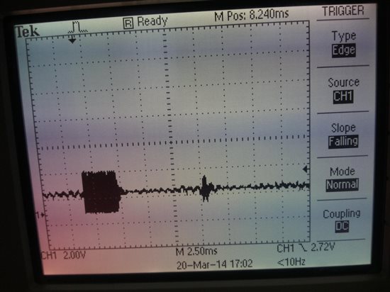
    3. Then Tunr ON the Amplifier Output (Unfiltered) and driven transducer with obstacle upto 1.5 meter & observe the waveform on TESTO_A pin, see the attached waveform.

    Which is showing burst with obstacle as mentioned in page no. 19 of EVM_User_Guide.pdf.

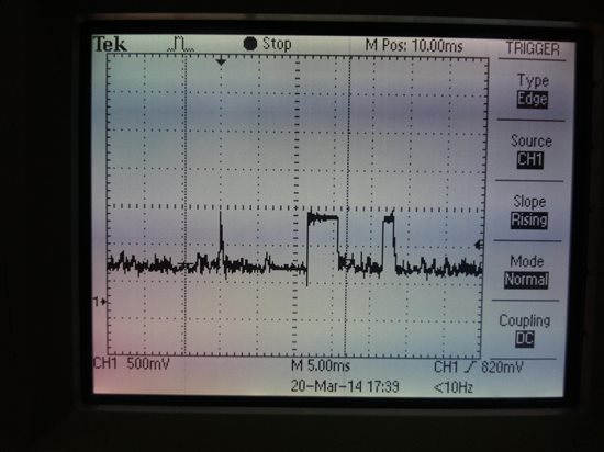
    3. Then turned OFF the Amplifier, and Turn ON the Datpath output(Filtered) and driven transducer with obstacle upto 1.5 meter, & observe the waveform on TESTO_A pin, see the attached waveform.

    Which is showing burst with obstacle as mentioned in page no. 20 of EVM_User_Guide.pdf.

    Also see the graph6 for the above step. 

    8688.Graph6.xlsx

    4. The I have Made Micro Active.

    5. Then in LIN Tab checked whether LIN is working fine or not by sending 2  bytes with 21 PID. I received back 0x12 34 which validates LIN was working fine.

    6. I had entered threshold values for short and long distance in EEPROM as per page.4 of demo write up for PGA450 with PID= 0x31.with databytes 0x(DC), 0x(6B), 0x(59), 0x(44), 0x(33), 0x(22) and 0x(11)

    7. Then I triggered Long distance transmission with PID=0x11 and Bytes 0x01.

    8. I observed waveform on TESTO_A. which is similar to point no. 3. 

    9. then tried receiving distance informtion with PID= 0x22 and Number of received bytes as 2, i got the distance 1.16m. this distance is varying as changing obstacle position but distance is not so proper. at least getting distance.

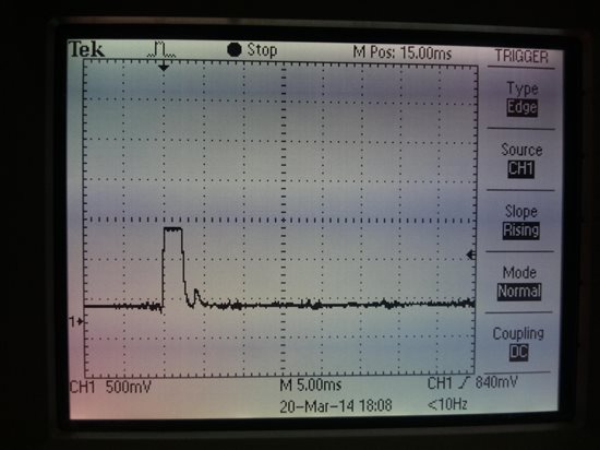
     10. But for Short range distance transmission with PID = 0x11 & Databyte = 0x00, and obstacle at 30cm I have observed waveform on TESTO_A as shown in attached waveform 

    Which is not showing any obstacle. and Distance in LIN tab is 0.15m. It is showing fix 0.15m distance for changing obstacle position. Also see the graph10 for this step as attached.

    1033.Graph10.xlsx

    Kindly request you to  have alook at these waveforms and excel plots and please let me know your feedback at earliest.

    - Switesh.

  • Switesh,

    Can you clarify what additional information you need about the PID command for slave devices?  The example firmware does not implement the slave node ID in the LIN PID frame.  The example protocol I explained above is one way that you can modify the firmware so that multiple slave nodes can operate on the same LIN bus.

    It looks like you need to tune the transformer on the EVM.  This is supposed to be done by the board manufacturer's before it gets to you, but it doesn't look like they did it correctly.  I've attached a document that walks you through how to do this.  Please be careful with the transformer, they are easy to break.

    Tuning the transformer will improve the matching, and help the energy to decay faster.  With the way the thresholds are set right now, they are almost immediately triggered, causing the false detect.

    PGA450Q1EVM_Tuning_Procedure v2.pdf
  • Hi Clancy,

    Issue_1

    Leave the first topic, will concentrate later on.

    Issue_2

    For second issue, In Evaluation Tab we have decrease the LNA gain to 40 dB, after that we are correctly receiving the echo for both long & short distance measurement. as shown in attached graphs 

    8357.Graph11.xlsx 

    3755.Graph12.xlsx

    but in the LIN tab, with the present firmware LNA gain is 63dB, which is amplifying noise too, so echo is not detecting correctly.

    Please tell me how to set the LNA gain to 40dB via LIN command? How the ESFR's are set by LIN inerface?

    Issue_3

    Can you please tell how to calculate the threshold values for long & short distance? i know the threshold levels are set by the LIN PID 0x31 followed by the 7 bytes of threshold values. which are written to the address 0x0400 to 0x0406 and in which lower nibble denotes the threshold values for short range & upper nibble for long range. I have not understood the point number 5 on page no. 2 & 3 of the Demo write up for use with Firmware Rev 2.1_B.pdf  .  

    Also i could not able to co-relate between set threshold values i.e. 0x(DC), 0x(6B), 0x(59), 0x(44), 0x(33), 0x(22) and 0x(11) and the graph that is plotted against FIFO sample numbers & Datapath Data. 

    with reference to the Datapath data in the graph, How to calculate 7 bytes of threshold values for short & long range distance measurement?

    issue_4

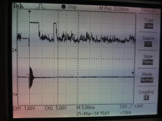
    You can see the waveforms at filtered output at TESTO_A pin  and waveform at IN pin as shown in following snap.

    in this snap you can observe the TESTO_A output showing burst and obstacle echo. this obstacle echo pulse is varying with respect to obstacle position. but  at the IN pin only burst is observing not the obstacle echo.

    How Datapath output TESTO_A shows the obstacle echo while the input to the datapath is absent?

  • Hi Clancy, waiting for your reply.

  • You are correct in that decreasing the gain causes the ADC to be saturated for a shorter amount of time.  How we got around decreasing the gain for short distance measurements is by adjusting which bits from the digital datapath are stored in the FIFO RAM.  By dropping the two LSBs for short distance measurements, the saturation threshold of what is stored in the FIFO RAM is increased, improving the shortest distance you can measure.  However, your method works as well.  We increase the gain to the maximum for long distance measurements so to maximize the farthest possible distance we can detect.  If you don't need to measure out to 5 or 6m, then decreasing the gain should be fine.

    Do you have the programmer's guide for the PGA450?  If so, that details what the register settings should be.  I can send it to you if you don't have it.  The sample firmware is not set-up to change the gain setting based on a LIN command.

    Issue 3:

    To calculate the thresholds, first remember that the upper nibble (the four most significant bits) are used for long distance measurements and the lower nibble (the 4 least significant bits) are used for short distances.  Convert this hex value into decimal, and then use the equations below:

    note: T = threshold programmed into EEPROM

    short: threshold = T*16 + 4

    long: threshold = T*8 + 12

    Issue 4:

    Consider the magnitude of voltages you're dealing with.  The signal from the IN pin is going through an LNA with a gain of 40dB, so it's hard to see echo pulses directly on the oscilloscope.

  • Hi Clancy,

    Thanks for your valuable comments.

    Issue_2

    The Sample firmware is not setup to change the gain settings by LIN command. Then to change the LNA_GAIN1  & LNA_GAIN0   from ESFR register CONTROL_1,  i need to change the firmware. it is right?

    Then tell me how to change the firmware? i am having PGA450 - Firmware Rev 2.1.1  which includes firmware software source files and PGA450.hex file.  which compiler should i use?


    Issue_3

    Yes, now i understood the threshold calculation. and correlation between set threshold values i.e. 0x(DC), 0x(6B), 0x(59), 0x(44), 0x(33), 0x(22) and 0x(11) in  EEPROM and the graph that is plotted against FIFO sample numbers & Datapath Data. 

    Issue_4

    so it's hard to see echo pulses directly on the oscilloscope.

    But looking at the waveform in the snap at channel 1 which is the signal at IN pin, while bursting  it is having approx 2.8 v  (peak to peak ) which is also amplified by 40dB gain by LNA. for this signal datapath output TESTO_A at channel 2 shows approx same 2.8 v output .

    Then at channel 2 which is showing obstacle echo pulse upto 2.8 v, why it is hard to see at IN pin at channel 1 ?

    if possible give the answer.

    Thanks for your reply.

  • Hi Clancy,

    I got answer for Issue_2 and Issue_3.

  • Hi Clancy,

    By changing LNA gain to 40 db in the firmware, i am getting the obstacle distances in LIN. but problem is in measurement of short distance. i am getting distances after 50 cm but not below 40 cm. please see attached graphs.

    For 120 cm 

    For 100 cm

    For 80 cm 

    for 70 cm

    for 60 cm

    for 50 cm

    for 40 cm 

    i have set thresholds to 0x(DF), 0x(6F), 0x(5F), 0x(4F), 0x(3F), 0x(2F) and 0x(1F) .

    below 40 cm it is not distinguishing burst & obstacle. 

    How to reduce this burst time?

    What thresholds to be set for these type of graphs?  

    Also

    Also above is the snap of evalution tab and EEPROM data. threshold are set upto 7 bytes. but after 7 bytes short distance threshold must be 4 as mensioned in the Demo write up for use with Firmware Rev 2.1_B.pdf   but EEPROM data shows 0xA  upto 767.

    How to set these to 4.?

    Please reply soon.

    - Switesh.

  • Hi Clancy,


    Waiting for your reply. 

  • Hi Clancy,

    Here is big confusion in setting the threshold value, please tell me in detail how to set the proper threshold values for short & long range.

    Today i have taken graphs in evaluation tab as attached below.

    6165.5-2-2014.rar

    Threshold has to be set as follows -


    Please observe the graph  40cm_12Pulses_Mid8bit.xlsx  for obstacle is at 40 cm, LNA Gain is 40dB, 12 Pulses and FIFO mode is Mid 8 bit. Graph shows obstacle detected at FIFO locations 58 to 66 with Th values 51-94-51. 

    Same for graph 50cm_12Pulses_Mid8bit.xlsx  obstacle at 50 cm, obstacle detected at FIFO locations 72 - 81 and Th values 43-87-37.

    For 60cm_12Pulses_Mid8bit.xlsx  60 cm , 86-94 and 28-72-37.

    For 70cm_12Pulses_Mid8bit.xlsx  70 cm, 102-109 and 27-60-31.

    For 80cm_12Pulses_Mid8bit.xlsx  80 cm, 116-124 and 18-42-25.

    For 90cm_12Pulses_Mid8bit.xlsx  90 cm, 133-139 and 25-37-24.

    All these are short range distance (15 cm - 1 meter).  as shown in above snap 7 bytes of threshold for short range is set from FIFO location 0 to 63 and after that 64 to 76 Th value is 4. But for actual obstacle is detected for short range at FIFO location greater than 63. 

    How to set the thresholds for all of these graphs?

    I have set threshold according to graphs to 0xFF, 0x3F, 0x1F, 0xFF,0xFF, 0xDF and 0xBF. but till i am not able to get proper distances via LIN tab.

    For Long range i have used LNA Gain is 40dB, 18 Pulses and FIFO mode is  8 LSB bit FIFO mode.

    Please reply soon. It is very urgent.

  • Switesh and I have discussed this issue further offline.  Here was my response:

    I’ve looked through your data and I have a few recommendations.  You mentioned that the LIN tab is reporting a distance of 15cm no matter what.  I’ve attached two versions of the threshold template that should help you visually see what is happening.  The first threshold template contains example data from our lab and has the recommended EEPROM threshold settings (from the demo write-up document).  The second threshold template ending with “MS data” contains your data and the thresholds you specified below.  There are two tabs in each spreadsheet, one for short distance mode and one for long distance mode.  The dashed yellow line is the threshold, and the example firmware will flag the first time that the echo data (the blue line) crosses the threshold as where an object is.  As you can see from the plots, your echo data is crossing this threshold early, which causes the incorrect distance measurement on the LIN tab.


    Are the excel plots from the evaluation tab, or did you trigger a distance measurement with a LIN command and then use the FIFO tab to export to excel?  The reason this might make a difference is that with the evaluation tab, the blanking timer is not set and the FIFO RAM is filled immediately instead of waiting for the decay to be done (line 130 in PGA450_isrs.c) which helps explain why the decay time is so long in the plots.  This makes the threshold templates I sent you inaccurate because the echo data is loaded into the FIFO RAM immediately instead of waiting for the decay to be done. 


    You can still use the evaluation tab to monitor the data, but make sure to check the “Invoke through LIN” checkbox to use the firmware.  When this box is checked, the evaluation tab will send the TX command entered on the LIN tab, then put the micro in reset to read and plot the FIFO data.  This is basically a quicker way to test the PGA450’s firmware, instead of having to manually put the chip in reset and export the data to excel from the FIFO tab.


    Copy and paste the new FIFO data you get into the template and you’ll probably still see that the threshold is crossed almost immediately.  There are a couple of ways to fix this:


    1. Change the thresholds in the EEPROM.  You can use the threshold templates I attached to help you with this.  Take some distance measurements with no objects in front, and set the threshold to always be above the data (to prevent false triggers).

    2. Change the thresholds in the firmware.  If the decay time is still too long, it’s possible that you’ll need to manually change the threshold algorithm in the firmware to get the values you want.  You can do this by hardcoding the threshold values into the firmware.  You’ve already mentioned that the threshold after FIFO location 63 is too small.  That is something you would have to change manually in the firmware.


    After saying all of that, it still looks like you might have other problems in your set-up.  For instance, the noise floor appears to be very high.  I expect to see a noise floor of around 0-2 for short distance mode and under 10 for the long distance mode. You can take a true noise floor measurement by doing the following steps:


    1. Load Rev 2.1 firmware

    1. Put the micro out of reset and send one long distance pulse

    1. Put the micro back in reset

    1. Write 0x01 to register 0xC3 (PWR_MODE)

    1. Write 0x00 to register C8 (EN_CTRL)

    1. Write 0x0C to register C8 (EN_CTRL)

    1. Read and Save FIFO data to file


      The reasons why the noise floor might be high could be due to the environment you’re testing in, or more likely the power supply for the EVM.  Try taking some noise floor measurements when using a 12V battery to power the EVM, a laptop powered off of its battery, and  nothing else connected to either the EVM or laptop.  Compare those noise floor measurements to the noise floors using your regular set-up. 


      If the decay time is still quite long (especially important for your short distance measurement), then you can make sure that the transformer/transducer combo you’re using is tuned correctly.  The capacitor C20 on the EVM is used for this tuning, and the equation for it is below:

      C_tune = (C_T*L_T)/L_sec - C_PT

      C_tune is C20 on the EVM, L_sec is the secondary inductance of the transformer, and C_T, L_T and C_PT are characteristics of the transducer which you can measure on an impedance analyzer.


      The decay time is also longer because you’re sending 12 bursts during the short distance mode.  We are able to get very good results using 1 burst and 64dB gain for short distance mode.  The 1 burst ensures the fastest possible decay time, which improves the minimum distance you can measure.

  • Hi ,

    i didn't understand how to measure distance from using graph , can you explain detail.
  • Hey Clancy,

    I have a similar problem as described above. The sensor is still busy with sending bursts, and the echo signal is already back and lost in the burst signal. The rang of interest is between 20cm and 70cm. Sending only one burst doesn't work because I don't receive an echo.

    My question is: Is it possible to use two ultra sonic sensors with PGA450: One as a transmitter for sending bursts, one as receiver to receive the echo? Is it possible to do so or does the receiver need a basic frequence signal, like a "dither mode" or something like that?

    Kind Regards

    Jan

  • You can use one sensor as a transmitter and one as a receiver. To do this with one PGA450, you would connect one transducer to the transformer and the other to the return signal path (to the IN and LIM pins). On the EVM schematic, you could remove the XFRM jumper (JP3) and connect the listening transformer there.

    Also note that you can experiment with the number of pulses to get the right range for your system. Fewer pulses will reduce the saturation time. You can also experiment with the FIFO_MODE. To achieve the maximum distance, you should store the lower 8 bits of data in the FIFO, but to reduce the saturation time, you can store the middle 8 bits in the FIFO RAM.

  • Is it possible to send another transmit pulse from the PGA450, which is timed to the initial burst pulse, but 180 deg out of phase.

    This will attempt to stop the transducer from resonating at its modal freq and shorten the composite burst envelope.

    See here:

    http://www.yashu.com/UltrasonicDelayedPulseShaping.jpg

  • Hi ,

    i didn't understand how to measure distance from using graph.

    more detail please !

  • Dear Clancy,

    I am using PGA450 for reverse distance sensing purpose in our automotive product.

    I have PGA450-Q1 Evaluation board with me.I am trying LIN communication using following commands -

    TX side -------

    1. PID= 0x11; data = 0x00

    Rx side-------

    1. PID = 0x21; receive databytes = 2;

    But the board is not communicating on LIN. I tried to see the waveforms on LIN bus , but it is still 12 V straight line. no data on LIN.

    I have enabled the 5V jumper setting means LIN in enabled chip pin 2 --> 5V.

    I am not getting how to proceed , it was working fine last time.

    could you help me how to enable the usart of the PGA450 .

    I am writing here the sample code i tried .Please go through,I am getting 5V data pulses on the TX pin of the PGA450 but no data on the out of DB9 TX pin.

    should i am missing something.

    //***********************************************************************************

    void main (void){
      Initialization();
      serial_init();
      while (1){
        
                  
                printf (" PS - PrimerC51 UART Demo\n\n\r");
                while (1)
                {
                printf ("hello world");   /* Print "Hello World" */
                      delay(8000);
                    

                }
        
        } /* Loop forever */
    }


    void serial_init(void)

    {

        SCON  = 0x50;                         /* SCON: mode 1, 8-bit UART, enable rcvr         */

        TMOD |= 0x20;               /* TMOD: timer 1, mode 2, 8-bit reload                    */

        TH1   = 0xFD;               /* TH1:  reload value for 9600 baud @ 11.0592MHz*/

        TR1   = 1;                  /* TR1:  timer 1 run                               */

        TI    = 1;                  /* TI:   set TI to send first char of UART           */

    }

     
    void delay(int j)
    {
        int i;
        for(i=0;i<j;i++);

    }

    //************************************************************

    thanks,

    Priyank

  • John,
    The PGA450-Q1 firmware enables users to configure the low side MOSFET gate drive mode's Number of Pulses (register(s) PULSE_CNT_x) and Low-Side frequency (register(s) BURST ONx_LSB/, BURST_OFFx, DEADTIME). Can you provide details on your implementation? We may be able to replicate your conditions in our lab to help test this.
    Thanks,
  • Hello Ayoub,
    See our new "PGA450Q1EVM - Part 3. Interpreting" video tutorial at:
    http://bcove.me/jbjvy5p7
    This video includes an explanation on how to interpret distance and convert data stored in and graphed from FIFO memory.

    Additional tutorial videos can be found under the "Videos" tab at:
    www.ti.com/.../support
  • How do I set the transmit signal phase?

  • John,
    There is no immediate register available to change the transmit signal phase. The aforementioned registers I listed could be configured in combination with additional delays to potentially emulate the effects of what would be a phase shift on a transmit pulse. We have not yet had an opportunity to test this ourselves, so there is no instruction/data to support the feasibility of this implementation. If you are willing to share your intended operating criteria, we can make an attempt at a proof-of-concept based on your setup.
  • Priyank,

    If the EVM is confirmed to be communicating with the GUI (you can read/write registers or program the PGA450-Q1), there must be a minor step being skipped when attempting to use LIN. Note that for LIN communication to work, the PGA450-Q1 microcontroller must be set to the active state (GUI’s ESFR tab --> ON (MicroActive) button) (this is a common error amongst users).
    We are releasing a visually supported LIN Demo Walkthrough of the PGA450Q1EVM GUI. While we wait for this document to be uploaded to TI.com, I can send you an email copy (please provide your email address). Confirm that you have followed the instructions of this document.

    Regarding UART operation, we released the TIDA-00151 UART Demo Firmware for PGA450-Q1 last month:
    www.ti.com/.../tidcab3
    You can use this source code as an example of how the PGA450-Q1 must be programmed in order to utilize UART communications on the PGA450-Q1 TI Design (TIDA-00151). We are also releasing an instruction guide on how to use the UART firmware example with the PGA450Q1EVM GUI. I can send you a copy of this document as well prior to its release to the web.

    Regards,
  • Dear Akeem, Would you send me "a visually supported LIN Demo Walkthrough of the PGA450Q1EVM GUI" at ymkim@dongiltech.co.kr? I tried to download TIDA-00151 UART Demo firmware for PGA450-Q1 but it apparently removed temporarily. Would you also send it to me? Best regards. Young Min Dong Il Technology, Rep. of Korea
  • Dear Akeem ,
    I tried to download the firmware for uart , but its not there on the website.
    But i managed to make it, its working fine now.
    And for LIN i am trying it with uC in on condition,
    I have gone through the firmware thoroughly, i know LIN is working on RX interrupt and cases are there to read the data and write values to EEPROM.
    But still its not working for me, i checked the hardware too with transceiver enable pin status etc....
    Kindly update.

    thanks,
    Priyank
  • Hello Young,
    The LIN Demonstration using PGA450Q1EVM Firmware Rev 2.1 is now available online under the Application Notes section of the PGA450-Q1 product page at:
    www.ti.com/.../technicaldocuments

    I have confirmed that the UART Demo FW is still actively available online. Have you had any success in obtaining this FW since your last update? If not, I will check on the export approval status since you are in Korea.
  • Dear ,
    I have gone through the same problem, as you are facing.
    whatever the value of threshold you set , you are getting a constant distance 20 - 30 CM ar any other value ... m i right?

    the reason i found is the curve is touched to your threshold value 255 that is FF in threshold.
    condition gets fulfilled in the firmware and its an object to the PGA450... this is the game behind it.
    :)
  • Hi,
    All these types of problem are due to non matching of transformer with the transducer.
    kindly check your transformer turn ratio, inductance etc.
    and the major role is played by the matching capacitor C20 in the board.
  • hello akeem ,

    First thank you for your help.

    I really need some information, I am trying to communicate with a PGA450 card with a microcontroller using SPI communication and I need to find the registers (addresses) to retrieve the data. I am having a hard time finding the right registers. Do you have any advice on how to do this?

    regards

    SLIMANI Ayoub

  • Hello akeem ,

    Waiting for your reply.

    regards

    SLIMANI Ayoub

  • Hello Ayoub,
    Have you downloaded the latest version (Rev. B) of the PGA450-Q1 datasheet uploaded in June? This version includes the Programmer's Guide, which provides the memory map and descriptions of each register (w/ hex address defined as offset =0xNN) and register bit. Is this the information you are seeking?
  • Hello akeem ,

    It's not exactly what I want, in fact I would like to make a SPI bus communication by communicating with a microcontroller and PGA450, and I need the right register addresses to send and retrieve data ( for SPI communication).
    Do you have any other documents or information on SPI communication specifically?

    regards
    SLIMANI Ayoub
  • Ayoub,
    I have answered this question on the appropriate post at:
    e2e.ti.com/support/applications/automotive/f/26/p/226046/1560522#1560522
  • Hi Clancy,
    Could you please explain a little more how the auto addressing is possible in 4 slave sensor system.
  • Hello Priyank,
    We have released an Application Note discussing how to perform auto-addressing in a multiple slave sensor system. Refer to "Automatic Slave Node Position Detection (SNPD) for PGA450-Q1" at: www.ti.com/.../slda038

    If you have any questions about the details of this document, let us know.
    (In the future, please create a new post for questions not related to the initial post.)