This thread has been locked.

If you have a related question, please click the "Ask a related question" button in the top right corner. The newly created question will be automatically linked to this question.

Looking for PMU for TMS570LC4357

Other Parts Discussed in Thread: TMS570LC4357, TPS62290, TPS62260, TPS65381-Q1, TMS570LS3137, TPS57112-Q1

We are in the process of designing a product that will use the TMS570LC4357. Other TMS570 microcontrollers have a low enough power consumption that allows the use of the safety-critical TPS65381Q1.

With the release of the TMS570LC4357 it appears to me that the TPS65381Q1 isn't capable of meeting the power demand.

What is the recommended PMU for the TMS570LC4357?

  • Gerald,

    There was some discussion about adding a standalone/separate switcher to provide the 1.2V core to the TPS65381 which would still allow the use of all the diagnostics in the 65381.  

    But I think since this is a question about the best power management solution we should move the post to the automotive forum which is where the 65381 chip is supported as you need a power management expert and not an MCU expert for this one.

  • Hi Gerald,

    I'm looking into this.  Our team has started to look into this but I have to contact the correct folks who are oversea's hopefully I can get an update in a few days to make sure I point you in the right direction for the external DC/DC. 

    Thanks for the patience.

    Scott

  • Hi Gerald,

    How soon do you need this?  We have some very rough concepts but not all the details are thought through and verified at this point.  Depending on your time line we can provide the concept now and details later as we work them or wait 3-4 weeks till we close on more details.

    - Scott

  • Scott,

    We are in the early stages of the project so we have some time.

    After running the thermal numbers based loading estimations using the TMS570LC4357 datasheet I came to the conclusion that the TPS65381 is marginal for 90C operation on FR4 board. For now we are going to move ahead with the "safety-compliant" PMU.

    Please let me know what changes are coming.

    Thanks,

    Gerald

  • Hi Gerald,

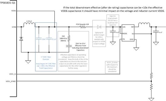
    Thank you for the patience on this one.  We have been working through using external DC/DC converters with the VDD6 rail on the TPS65381 device.  Because the VDD6 switcher is a hysteretic mode converter it needs capacitance with ESR on the VDD6 node, however most DC/DC convertors require low ESR input capaitnace which contradicts the output capacitance requirement. Below is a basic schematic with some guidelines outlining how to use the TPS65381 with a downstream DC/DC instead of the VDD1 LDO.  We wanted to make sure the VDD6 output operated as expected with these requriements.  We have looked at a few devices for the downstream DC/DC such as the TPS62232(-Q1), TPS62260(-Q1) and TPS62290(-Q1) depending on how you are using the TMS570 and the maximum load you will pull for your applicaiton with the MCU. 

    After re-reading your thread this time it seems you may also be asking to power a DC/DC for the core voltage seperately from the TPS65381 completely. If this is the case are you asking which one or how to possibly use the TPS65381 for FS coverage?   Are you assuming the ~1A max Icc for the TMS570 and then how many other rails do you need (voltage and current)?  

    - Scott

  • Hello Scott,

    Can I ask if you have any remarks to be added about your post above?

    My customers are looking for a power solution for the TMS570LC4357. Therefore I would like to recommend your circuit.


    -n


  • It will depend a little on your system level desires.  What is your loading on the various rails besides the TMS570LC4357 and will you be using the TMS570LC4357 to max? 

    The TMS570LC4357 is specified to need up to 990mA on the digital supply which would use up most of the VDD6 pre-regulator's 1.3A capability from the TPS65381.   

    What is your input supply?   If I know the current budgets on each rail and input voltage we can try to come up with something.

    - Scott

  • Scott,

    We use one isolation stage to meet safety isolation requirements to generate a 15V output to power downstream blocks.

    In our application the 15V distributed bus powers our digital core and power drivers. Our intent was to use the TPS65381 (or similar) to meet the critical safety requirement of monitoring the power supplies for the digital core that is used to control the power drivers.

    According to the power budget the digital core needs the following power.

    1.2V = 1000mA

    3.3V = 400mA (includes the TMS570 and all interfacing I/O)

    5.0V = 200mA (communication ports and off board interface)

    Right now we are using separate regulators to off load the TPS65381, as shown below:

    TPS65381 1.2V = 1000mA

    TPS65381 3.3V = 200mA

    TPS56381 5.0V = 50mA

    3.3V_IO = 200mA

    5.0V_IO = 150mA

    So ideally we would like to have the complete digital core powered from one PMU.

  • * Gerald, please forgive me this post is conflicting to yours.

    * Could you please clarify the worst case current? It would require Gerald a re-calculation.


    ======================================

    * This is a reply to Scott.


    > What is your input supply?

    It is 24V battery. But the VBAT is sometimes 5V, therefore the TPS65381-Q1 input would be pre-regulated by a buck-boost.


    > will you be using the TMS570LC4357 to max? 

    Unfortunately Yes. The 1.2V Iout assumes the TMS570LC4357 maximum (TBD) including flash memory operation current = 93mA.
    Could you please clarify the worst case current? For example TMS570LS3137, the worst case is not (operational) but (LBIST) and (PBIST).


    > The TMS570LC4357 is specified to need up to 990mA on the digital supply which would use up most of the VDD6 pre-regulator's 1.3A capability from the TPS65381. 

    We put the extra buck converter for 1.2V. In the case I think the VDD6 doesn't collapse. Instead the problem would be the extra 1.2V buck converter.
    Which part do you recommend as the extra 1.2V buck regulator?


    -n


  • Gerald,

    I reminded you are the owner of this thread. I would like to move to a new post if this doesn't close today.


  • Hi Hideaki Nambu,

    By Buck-Boost pre-regulator what is that voltage that would be the input to either TPS65381 and/or it plus an additional converter?  It appears the rail is already pre-regulated down so we wouldn't need to consider a high voltage input capable regulator for your case.

    We are thinking of using the TPS57112-Q1 directly from the VDD6 of TPS65381.  I will be working up the example with the system requirements from Gerald and you can see this example when I get it done tomorrow.

    I'm not in the TMS570 team but the PMIC team so I don't know the max current when LBIST or PBIST is run.  I will try to see if the MCU team has an update. 

    - Scott

  • Gerald,  scrap the last post.  I was thinking with LDO's not DCDC.  I'm working a concept with TPS57112-Q1 which should work for you and I think allow all the system current to be through TPS65381 pre-regulator. I will try to finish it and more calculations tomorrow to make sure there is enough output current from the TPS65381 to handle the full load. 

    - Scott

  • Using these assumptions we could approach this using the TPS65381 as the main PMIC and then use a TPS57112 as a downstream DCDC converter for the TMS570 instead of the VDD1 LDO controller.   http://www.ti.com/product/tps57112-q1?keyMatch=tps57112&tisearch=Search-EN

    The TPS57112 is a 2A capable output DCDC converter.  If the input is supplied by the VDD6 pre-regulator of the TPS65381 we can make a few assumptions about input voltage to output voltage and get the load current impact worst case on the VDD6 regulator.  I have added the option for a series diode to drop the votlage further from VDD6 output to add margin for the absolute max range of TPS57112 (7V abs max, vs 6.6V max output of TPS65381).  The table below maps some assumptions on these rails to get to a worst case load on VDD6 of about 404mA if it operates all the way down to minimum Vbatt input of 4.2V.

    TPS57112 with series diode for VIN margin
    Parameter Level
     Vdrop Diode drop   0.7 V
    VIN VDD6  min 4.7 V
    nom 5.3
    max 5.9
    UV max 3.8
    UV min 3.5
    VOUT     1.2 V
    Iout   app load 1000 mA
    Efficiency     0.85 percent
    Iin
    (VDD6 load)
    VDD6  min 300.3755 mA
    nom 266.3707
    max 239.2822
    UV max 371.517
    UV min 403.3613
    Iout Max load   2000 mA

    We could make the following assumptions on the application voltage rails and current splits:

    Voltage Regulator VDD6 Load Current (max) Current Margin  
    5V VDD5 200 150 mA
    3.3V VDD3 300 50
    VTRACK 100 0
    1.2V TPS57112 403.3613 N/A
    All Loads VDD6  1003.361 296.6387

     Please confirm if splitting the rails up this way would work for you and I can take the first shot of drawing up a basic schematic, it would be similiar to the one provided a while ago when this started.  I am also ordering some TPS57112 EVMs to try this by bridging the EVMS together in the lab.

    - Scott

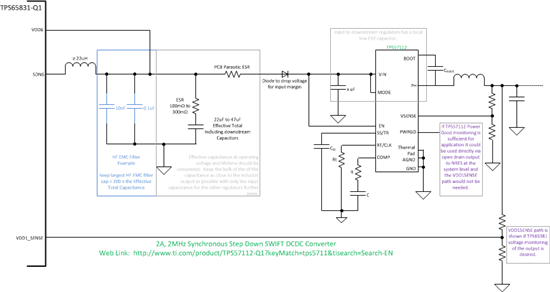
  • Hi Gerald and Hideaki, 

    Below is a schematic viewpoint of the DC/DC connections between TPS65381 and TPS57112.  If the power good levels in TPS57112 are adequet for your system you could use the power good monitor of TPS57112 which is open drain and connect it into NRES of the system. I have shown an alternative using the VDD1SENSE of TPS65381 as an alternative.  If you can use the TPS57112 power good it would free up VDD1 and that could also be used instead for the 3.3V rail or some of the 3.3V rail requirements.

    - Scott

  • Hideaki,


    Sorry, but I'm not understanding your question about "Could you please clarify the worst case current?"?

    I'm assuming that you are asking how I arrived at the preliminary power budget?

    It shocked me at how high the core power demand is. According to the datasheet "SPNS195A-FEB 2014, Revised MAY 2014", section 4.7, pg 59.....the core current (Icc) is 510 (typ) / 990mA (max), plus a few TBDs.

    So I rounded up to 1000mA.

  • Scott,


    That seems like a lot of board board area, but if that is our only option for now we will consider it.

    Do you know if TI is working on a new PMU that can support the TMS570LC3475 as a one-chip solution?

    Thanks,

    Gerald

  • Hi Gerald,

    There is a roadmap PMU that will have enough current capability for the TMS570LC3475 core as a one-chip solution and enough other rails that most safety systems should be covered.  However it isn't available immediately and details would need to discussed via NDA with your local field sales team's support.

    If you want less flexibility on the DC/DC for the core we may be able to find a converter that uses less components and could still provide at least 1A for the TMS570LC3475.  We have some 600-750mA solutions we were using to gain the efficiency even with MCUs needing less current, but the 1A plus some head room means those solutions didn't fit. 

    - Scott

  • Sirs,
    Can I ask the status of a PMIC for TMS570LC4357, again ?
  • Hi Nambu-san,

    This version of a PMIC isn't available immediately and details would need to discussed via NDA with your local field sales team's support.

    The PMIC as outlined above with DCDC has been in production for some time. The next generation PMIC in this family is close to production, but will also need an external DCDC for this specific TMS570 device that needs the higher core current. Details about it can also be learned under NDA through your local field sales and FAE team.

    Scott