This thread has been locked.

If you have a related question, please click the "Ask a related question" button in the top right corner. The newly created question will be automatically linked to this question.

Absolute-maximum-rating value of REF5045-Q1

Other Parts Discussed in Thread: REF5045A-Q1, REF5045

Dear, All

It is a question about 'Vout pin' of REF5045-Q1.
At the time of abnormalities, the seal of approval of the negative voltage may be carried out to 'Vout pin' from the exterior.
It is indicated as '30 mA' to the absolute-maximum-rating value of 'Vout pin'.
Does this mean that it is satisfactory if a current value is '30 mA' regardless of the impressed electromotive force to Vout?
Or is there any minimum voltage of negative voltage?
In a certain case, please let me know the voltage.

Thanks, Masami M.

  • Hello Masami,

    With regard to sinking short-circuit current, refer to Figure 12 of the datasheet, where you will find a maximum value of 20mA. By default, the short-circuit current condition configures VOUT=0V. To better understand your request, can you use Figure 12 as a visual reference to your question (if applicable), and numerically define the input/output conditions. If you can draw a schematic with the intended use case, this will be of most help.

    Thanks,

  • Hi, Akeem-san

    Thank you for the reply.
    The contents of the question change a little and there are the following two questions.
    It is the 1st.
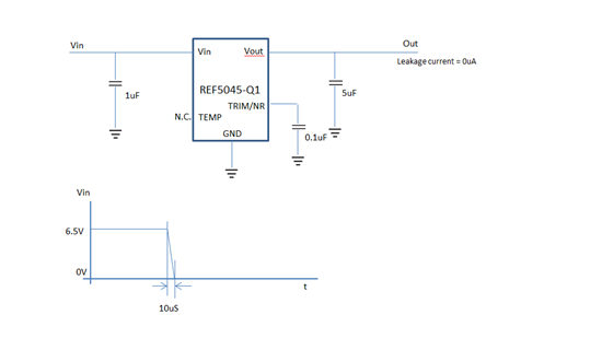
    It is considered as the circuit of the following figure.

    When the input side power supply short-circuits and voltage change of a figure is carried out, does REF5045-Q1 break? 

    It is the 2nd.

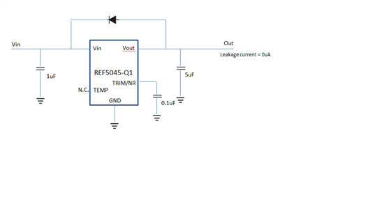
    Does the circuit configuration of the following figure have an inconvenient thing?

    Thanks, Masami M.

  • Masami,

    With regard to your first circuit, the most important factor that will determine whether the part is damaged during a short circuit condition (provided that the output can safely drive current) is if the junction temperature (Tj) of the output device exceeds the maximum rating (in the case of the REF5045A-Q1, TjMAX = 150°C). The fixed thermal resistance value of the package and ambient temperature dependent power dissipated yields what Tj in the short-circuit condition. The REF5045A-Q1 thermal resistance (Θja) of the SO-8 package is 150°C/W. Using equation 4 from the datasheet, we can calculate how the junction temperature’s worst case thermal condition is reached:

     Tj = TA + PD × Θja

    where

    PD = PQuiesent_MAX + POUT_XSTR

    where

    PQuiesent = Vs+  × (IQuiescent_MAX)

    POUT_XSTR = VOUT_XSTR (ISC)

    For example, if TA = 25 °C (or room temperature), then:

    Tj = 25°C + (117.5mW) (150°C/W) = 26.8°C

    where

    PD = PQuiesent_MAX + POUT_XSTR

    where

    PQuiesent = Vs+  × (IQuiescent_MAX) = (5 V) ( 1mA) = 5mW

    POUT_XSTR = VOUT_XSTR (ISC) = (4.5 V) (25 mA) = 112.5mW for a short to ground

    Now solve for the maximum allowable power dissipated before worst case thermal conditions will cause the device to fail at the maximum operating temperature (125°C):

    PD = (Tj – TA)/ Θja = (150°C-125°C)/ (150°C/W) = 167mW.

    As long as the power dissipated is below 167mW, the device should not be damaged immediately. I say “should” because the thermal path from ambient to the device junction involves a series of the thermal impedances, which include resistance and capacitance, having individual time constants. Initially, Tj may actually rise quickly during a short-circuit condition and then drop to a lower steady-state level once the dwell time has exceeded all the thermal time constants. The heat at that point is being transferred to the ambient environment via conduction and radiation. Based on the data available, I cannot definitively quantify how long the device will operate in the short circuit condition before failing or becoming damaged.

    With regard to your second circuit, there is no major concern of placing a diode between V_In and V_Out. I monitored the typical performance of a similar voltage reference, to find the output did not behave any differently with and without the diode.

  • Hi, Akeem-san

    Thank you for your reply.
    Please tell me another.
    When an input side power supply short-circuited, it's considered that VOUT becomes higher in voltage than the voltage of VIN, but is there a no problem?

    Thanks, Masami M.

  • Hi, Akeem-san

    Thank you for the reply.
    A shortstop on the input power source side be not a short circuit of 10uS, tell me the case which continue short-circuits after event, please.

    Thanks, Masami M.

  • Masami,

    You are absolutely correct, the TINA simulation does not demonstrate the effect of a short-circuit on the device. The correct representation is shown in Figure 1, however, TINA throws an error: "Convergence problem. Check the analysis parameters!"

    Please ignore the previous/erroneous TINA example. I will submit a pin-FMEA (Failure Mode and Effects Analysis) for this device to collect real data. I will provide results once available.

    Regards,

    Figure 1. Correct example demonstrating a short circuit of VIN to GND

  • Masami,

    As an update on this effort, we have ordered multiple samples of the REF5045-Q1 device to begin the short-circuit tests as early as next week. To summarize the problem statement, here is what we will be testing for:

    "If the V_In pin experiences a continuous short to ground, will the device become permanently damaged? If so, what is the duration the device will work in the short-circuit condition before completely failing?"

    Is there any other data point you'd like to have captured?

  • Hi, Akeem-san

    Thank you for the reply.
    It's OK by the item to which you were shown.

    Thanks, Masami M.

  • Masami,

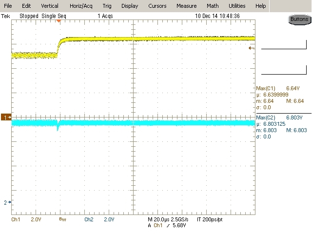
    Here are the results as tested on five units:

    1. “When the input side power supply short-circuits and voltage change of a figure is carried out, does REF5045-Q1 break?

    No, the device survives in both cases: Vin shorts to GND or Vout. Plots attached below:

    Figure 1. 2_VIN_Short_GND__6p5V__0__68uF

    Figure 2. 3_VIN_Short_Vout__6p5V__0__68uF

    2. "When an input side power supply short-circuited, it's considered that VOUT becomes higher in voltage than the voltage of VIN, but is there a no problem?”

    No, Vout does not become higher when Vin is shorted to GND.

    Throughout the tests, the Short Circuit Current was observed to be around 25mA (typical) as specified in the datasheet.

    Regards,

  • Hi, Akeem-san

    Thank you for the reply.
    I'm satisfied with a result no problem.

    Thanks, Masami M.
  • Hi, Akeem-san

    Thank you for the reply.
    Please inform me about below.
    - Please show me the figure into which Vin of 'Figure 1. 2_VIN_Short_GND__6p5V__0__68uF' expanded the part which falls in 1V from 6.5V.
    When there is current waveform of that case, please show it to me.
    - REF5045 is 4.5V output, but the voltage of Vout is 5.374V in 'Figure 1. 2.
    Please tell me a reason.
    - Can I think an electric charge of Capacitor on the Vout side flows back on the Vin side through REF5045?
    Can I think "This electric current is 25mA (typ), and it's within the 'ABSOLUTE MAXIMUM', so a problem doesn't occur."?

    Thanks, Masami M.

  • This discussion has been moved to an email thread.