This thread has been locked.

If you have a related question, please click the "Ask a related question" button in the top right corner. The newly created question will be automatically linked to this question.

PGA450 - ISSUE

For Long distance TOF: 1550

For Short distance TOF: 0378

Jumper Setting:

VPWR:VOTP       Close

VPWR:VLIN        Close

JP4                         Close

JP5                         Open

JP3                         Close

R2                           0 ohm resistance installed

 We are using LIN tab and start communication as per “EVM Demonstration using PGA 450 Firmware Rev 2.1” document. Steps which we are following:

  1. Load the Hex file in PGA450.
  2. Release the micro out of reset.
  3. Check the LIN communication, by clicking the RECEIVE button with PID 21 and data byte 2. In result, we have received 1234.
  4. We program the EEPROM through LIN TRANSMIT as per threshold valve: DC, 68, 59, 44, 33, 22, 11. Also we have checked these valves in EEPROM at location address 00 to 06.
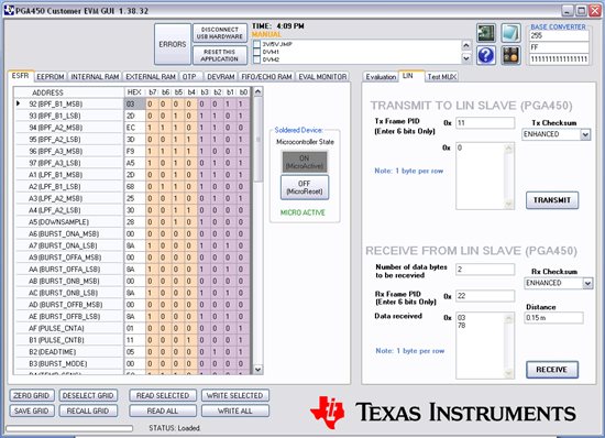
  5. Now, we transmit PID 11 and data 0 for short distance measurement and Data Receive using PID 22 and byte 2.
  6. We are repeating step 5 many times with different-different Object distances. But we are getting same result (distance = 0.15 meter) in the GUI.  
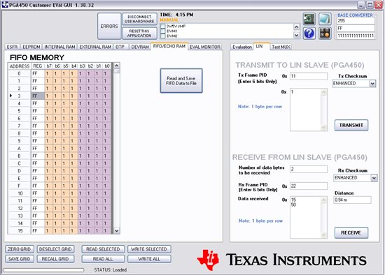
  7. Same steps for the Long distance to change the data 1 with PID 11 transmit and we are getting same result each time.(distance= 0.94 meter)

how to solve this problem?? 

  • Vinoth,

    The appropriate applications engineer has been notified of this post, and will respond accordingly.

    Regards,
    Eric
  • Vinoth,
    Your jumper settings are correct; however, note that the OTP programming voltage should not be applied for an extended period of time. Can you post a plot of the FIFO data for both the short and long distance runs? Your issue may be related to noise or transformer tuning; we'll need to analyze the data first. Also, can you provide a screen capture of your Evaluation tab to display the Transducer Transmit and Receive Settings?

  • Hi Akeem Whitehead,

                       Thank you. we still facing the same issue as mentioned above. the actual main problem what we thinking is the Object not detecting but we checked the transformer output and TEST0_A output , these outputs we checked and compared with user Guide document and Tuning document, but the TEST0_A outputs is initially decay time signal and then some noises we getting .

    1. we did not connect OTP jummber.

    2. we using the sigle-ended transformer and 40 KHz transducer.

    6201.Short Distance.xlsx

    0815.Long Distance.xlsx

  • Hi Akeem Whitehead,

                       Thank you. we still facing the same issue as mentioned above. the actual main problem what we thinking is the Object not detecting but we checked the transformer output and TEST0_A output , these outputs we checked and compared with user Guide document and Tuning document, but the TEST0_A outputs is initially decay time signal and then some noises we getting .

    1. we did not connect OTP jummber.

    2. we using the sigle-ended transformer and 40 KHz transducer.

    2072.Short Distance.xlsx5706.Long Distance.xlsx

  • Vinoth,
    Can you send us the oscilloscope screen captures of the transformer output and DACO (TESTO_A) output?

    A single-ended transformer exposes the transducer to a DC equivalent voltage, and is not balanced like a push-pull transformer's negative-to-positive swinging voltage. As a result, the decay time may be longer for the single-ended transformer. The long distance waveform results you've shared indicate that the FIFO is storing saturated data. You'll need to configure the registers to store data after the initial decay period. If you used the default Blanking Timer of '0' on the Eval Tab, this may explain the extreme values of the data you're collecting. Here are my suggestions:

    • For the long distance measurement, try setting the Blanking Timer to the maximum value of 0xFF(or 255 in decimal).

    • For the short distance measurement, try setting the Blanking Timer to the longer value of 0x27 (or 39 in decimal). If this has no impact, increment the value until you do observe a difference (if any). Does lowering the LNA Gain factor for the short distance measurement make any difference?

    • Ensure the Enable Control (EN_CTRL) Register's BIT 3 ECHO_EN = 1 (Enable echo processing – the FIFO starts filling after the blanking timer expires).