This thread has been locked.

If you have a related question, please click the "Ask a related question" button in the top right corner. The newly created question will be automatically linked to this question.

ULQ2003A-Q1 Inductive Load Driving

Other Parts Discussed in Thread: ULQ2003A-Q1, ULN2003A

Dear , Sir.

My customer  want to utilize ULQ2003A-Q1 internal diode against the reverse voltage

as flywheel. I would like to confirm following 2 things in addition to the question which other person

has been asked already.

1. I undrstand the break voltage is 50V.

   The reverse voltage duration will be quite short time.

   Do you have another robustness spec specified just as transient time?

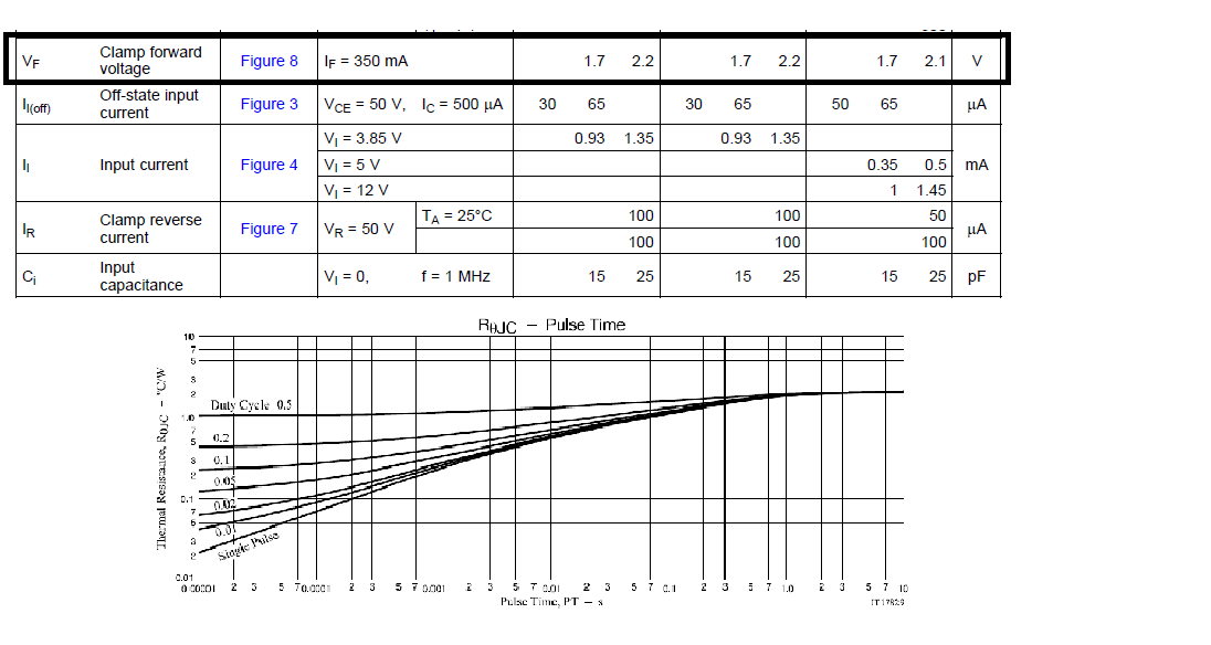
2. I understand the total thermal dissipation for Vf is significant.

  The customer don't use it under PWM operation. It means that the flow is just kind of

  single and short time.

  Do you have the derating factor of power dissipation considering such kind of condition?

I am expecting to get your advice at this time.


Best Regrads,

H. Sakai

  • Hideyuki-san,

    The diode can withstand at least 50V when reversed biased; this is when the transistor is on (output low).
    The diode's forward voltage (1.7V typ) is not much greater than the transistor's VOL (1.2V). [350mA data sheet table]
    The current in the inductor decays in a short time then the power dissipation will be lower because the channel is now off.
    Therefore for non PWM no special consideration is needed.
  • Dear, Ron-san. 

    Thank you so much for your teaching. 

    I would like to explain the background of my question, again. 

    As you know, When Low-side(of relay coil) transistor was switched ON to OFF, The 

    reverse voltage would be appeared due to L behavior. 

    Normally, Flywheel diode will be located in parallel with L to circulate the energy to

    supply side. 

    My customer want to utilize the internal diode instead of external flywheel diode. 

    The influence of diode turn on delay, Higher voltage will be applied on the output pin

    even if quite short time. 

    The coil inductance will be around several 10mH, and the resistance will be around 

    several 100ohm. 

    I would like to ask again. 

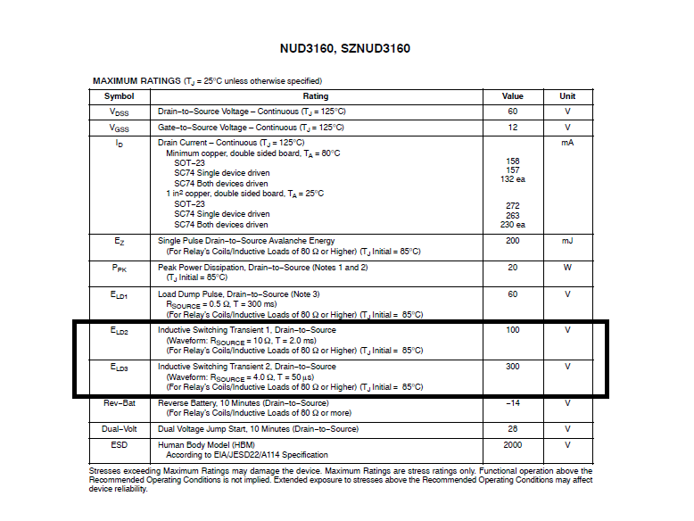
    1. MM ESD robustness is over 200V. 

       I wonder you may say the over voltage robustness on output pin in transient will be around 200V?

    I am expecting to get your advice one more time. 

    PS) Our competitor is defined such spec considering such situation. 

    Best Regards, 

    H. Sakai

  • Hideyuki-san,

    Do you know the parasitic capacitance of the inductor or it's self resonant frequency?

    For relays and stepper motors the self resonance is frequency is low enough that the diode turns on and limits the output voltage to about 2V greater than the inductor supply voltage.

    In addition, the turn off of the output transistor is not instantaneous. The base collector capacitance of the output NPN transistor causes it to turn off in a finite amount of time.

    I have not seen VOUT exceed VCOM by more than 2V except for some hot plugging tests for the inductive load. The ULN2003A survived this test while other NMOS based drivers were damaged by this abusive testing.

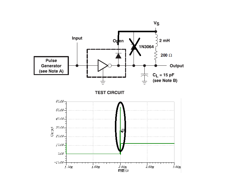
    The wave form you supplied looks like a simulation. Has there been any overshoot observed with the customers inductor?
  • Dear, Ron-san. 

    Thank you for your reply. 
    Sorry. I don't know the parasitic capacitance because the relay datasheet doesn't 
    describe the impedance graph. 
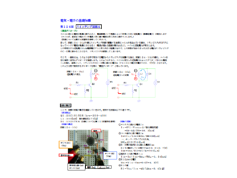
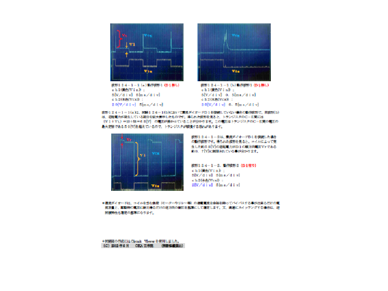
    The reverse voltage(逆起電圧) is different from resonant behavior, It is caused
    due to the coil(inductance) reaction that try to keep current flow soon after the
    current decrease. 
    I attached a simulation result on my previous mail. 
    At this time, I will try to attach the popular documentation about reverse voltage(逆起電圧), 
    not customer side information. However, the situation is same. 
    I am hoping to get your understanding. 
    Best Regards, 
    H. Sakai
  • Hideyuki-san,

    Those pictures were helpful. The first two wave forms did not use a diode and there was a large overshoot at turn off. The last waveform shows the the diode limited the overshoot to "Vf".

    It does not matter if the diode is external or inside the ULN2003A. It will work the same.

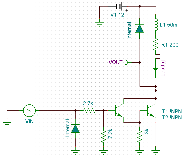
    Here is my TI-Tina (free software) test schematic for ULN2003A

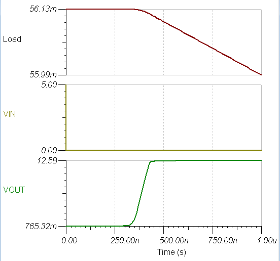
    Here is the the turn off wave form over shoot. The voltage is very controlled.

    I also attached the simulation file.

    ULN2003A Turn off.TSC

  • Dear, Ron-san. 

    Thank you so much for your valuable simulation model. 

    I have already checked it, Thank\s a lot!!

    BTW, What do you think how much voltage robustness would be reasonable on 

    ULQ2003A-Q1 output pin if the internal diode was used?

    Best Regards, 

    H. Sakai

  • Hideyuki-san,

    Maximum output voltage and maximum diode reverse voltage are specified as 50V.

    On average breakdown is about 90V, but any usage over 50V violates the data sheet and may cause damage.

  • Dear, Ron-san. 

    I am feeling a mount of gratitude for your information disclosure. 

    I am concerning the unexpected higher over-voltage due to turn-on delay on internal diode. 

    I understand the real peak will is totally depended on a coil inductance, resistance, 

    parasitic capacitance. 

    Below is the WEB information about diode turn-on consideration(Sorry, it is in Japanese). 

    URL : ednjapan.com/.../news082.html

    Sorry again, But do you have a information about the turn-on delay on internal diode?

    Best Regards, 

    H. Sakai

  • Hideyuki-san,

    I will study the article after the holiday weekend. I have inline translation to read it.
  • Dear, Ron-san.

    I've found the original documernt on LTC's web site.

    Please refer it in English, easy to understand for you.

    Sorry again.

    an122f.pdf

    Best Regards,

    H. Sakai

  • Hideyuki-san,

    I remember seeing this document in the past. It was a good read even the second time.

    The reason application note doesn't relate to the ULN2003 because the output turn off time is slow compared to a standard diode turn on time. In addition, the voltage tolerance of the ULN2003 is very good (50V). The diode overshoot in the application note is around 1V.

    The ULN2003 has been around for decades and time has proven that this device is robust and reliable.
  • Dear, Ron-san. 

    Thank you for all of your advice. 

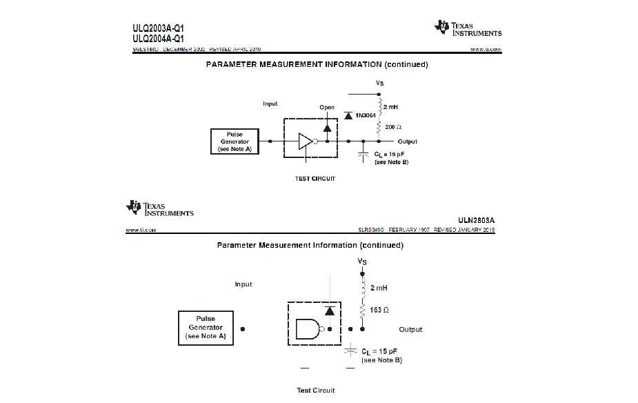
    Another device such as ULN2803A's datasheet includes the testing circuit 

    information utilizing the internal diode for flywheel. 

    If ULQ2003A-Q1 had similar one, It would be quite useful and reliable. 

    Best Regards, 

    H. Sakai

  • Hideyuki-san,

    I agree that it would be best if the data sheet used it's internal diode in all the drawings.
    It will be corrected in time, I will add it to the update queue.
  • Dear, Ron-san. 

    Thank you so much for your mentioning. 

    I will try to talk with my customer. 

    Best Regards, 

    H. Sakai