This thread has been locked.

If you have a related question, please click the "Ask a related question" button in the top right corner. The newly created question will be automatically linked to this question.

PGA450-Q1 GUI interface with MSP430 launchpad(instead of TI-GER board)

Other Parts Discussed in Thread: PGA450-Q1, PGA450Q1EVM, MSP-EXP430F5529LP, MSP430G2553
Hello everyone,
We are facing some issues in our set up.i have listed them out below.Help us in clarifying it.
1.We have connected PGA450-Q1 board  which is designed  by us with one of the TI,s EVM which is MSP430 launchpad using SPI interface.but the issue is when we  power up the launchpad through USB the GUI is not detecting MSP430 launchpad.It's showing as "UNKNOWN".
2.Is there any set up need to be done for the SPI on the MSP430 launchpad.As mentioned in document (SLDS185A)  SPI Interface section is there any need to send values or command to program into DEVRAM or OTP etc.
Only 3 lines are been used- MOSI,CS,CLK in SPI.
Regards,
Sanath Rai
  • Hello Sanath,

    The PGA450-Q1 GUI is only compatible with the TI-GER board that ships with the PGA450Q1EVM. There is currently no support to use the GUI with the LaunchPad platforms.

    Pages 48 to 51 of the PGA450-Q1 datasheet describe the SPI protocol and command sequence necessary for testability / programming. You must manually write the code for the MSP430 using Code Composer Studio (or other compatible IDE of your choice). Refer to your specific MSP430 family's Code Examples (i.e. if using the MSP-EXP430F5529LP, then see MSP430F552x C Examples (IAR and CCSv4) ) to help setup and execute SPI functions.

    Provide your email address so I can send you a copy of the PGA450-Q1 Programmer's Guide for detailed register information.

  • Hello Akeem,

    Thank You for the Response.

    I have MSP430G2553 launchpad.

    So you are saying that i need to dump the HEX file into PGA450-Q1 board using SPI protocol after writing the code for my Launchpad controller?

    I have got the PGA450-Q1 Programmers guide.

    Thank you,

    Sanath Rai

  • Sanath,
    Correct, you can essentially copy the contents of the HEX file into an array of your MSP430 code to load the PGA450-Q1's internal 8051 via SPI. We will be releasing an example Code Composer Studio project to demonstrate the MSP430G2553 LaunchPad HEX upload method to program the OTP and EEPROM of multiple devices at once. For the time being, we recommend that you continue to upload the HEX file using the TI-GER board and GUI combination (especially when leveraging the reprogrammable DEVRAM for evaluation).
  • Hello Akeem,

    Thanks for the response.

    Can we order just the TI-GER board so that we can interface it with our PGA450-Q1 board(designed by us).

    or do we need to buy PGA450-Q1 EVM to get the TI-GER board.

    Thank you,

    Sanath Rai

  • Sanath,
    The TI-GER board is not available for purchase as an individual item. You must purchase the PGA450Q1EVM to obtain the supporting TI-GER board.
  • Hello Akeem,

    We have purchased the PGA450-Q1 EVM.

    When we dump the example Hex file to DEVRAM provided by TI the code is successfully Dumping int it.

    But the hexfile created from the code written by me its showing the following errors.Any particular reason that you can think of?

    i have changed the necessary settings in keil software tool exactly as the example code provided by TI along with STARTUP.A51 file for DEVRAM.

    Can you help to resolve this issue?

    following are the errors on GUI tab

    ERROR - DEVRAM was NOT successful. Please check the 'Error' Tab for more information
    ERROR - Register 0005, was programmed to: 9A, but read back: 00
    ERROR - Register 0004, was programmed to: 20, but read back: 39
    ERROR - Register 000D, was programmed to: 73, but read back: 00
    ERROR - Register 000C, was programmed to: 21, but read back: 24

  • Sanath,

    Since the DEVRAM HEX file TI provides loads to the PGA450-Q1 and runs without error, I assume you already took into consideration section 10.6 of the EVM User's Guide:

    For a pristine IC that has never been programmed (OTP Status reads "OTP Empty"), in order to run software from DEVRAM, the OTP memory must be programmed with some specific instructions to redirect the 8051 μP to DEVRAM. This must only be done once. To do this, check the "Program OTP Memory Also" button, and the GUI will program the OTP with this jump statement as well as program the DEVRAM with the selected HEX file.

    Can you confirm that the OTP Status reads "Programmed to Jump to DEVRAM"? Can you also reconfirm that you have applied all the required changes to the Keil uVision settings for DEVRAM operation (see attached)?


    Keil uVision Settings for DEVRAM or OTP Memory.pdf

  • Hello Akeem,

    The hex file created by my code is dumping now but verification is coming as not successful.

    So for now i decided to test the hexfile given by TI ,i also have the entire project of the TI hex file.

    but for testing the TI hexfile any Hardware(PGA450-Q1 EVM) settings needed?

    i have closed the VPWR:VOTP jumper and also VPWR:VLIN jumper.

    The transducer given with Evaluation Module set  is connected to OUT:GND(P6)(No OUT pin and GND pin mentioned).

    In GUI i have followed the procedure given in one of the document i got from TI's Application Engineer(PGA 450-EVM Demonstration using

    PGA 450 Firmware Rev 2.1).i am stuck at step 6(Page 7) where i need to check LIN communication i am not receiving back any data.

    Thank You,

    Sanath Rai

  • Hello Akeem,

    We are testing PGA450-Q1 EVM through LIN communication using the GUI.

    But for both short distance and Long distance we are getting constant values even though we vary the object distance.

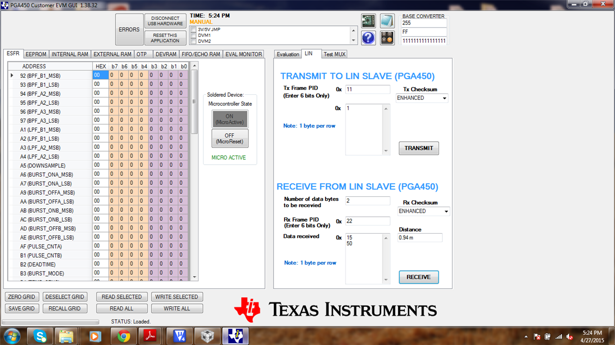
    Value for Long Distance - Data received 0x1550,Distance=0.94 m

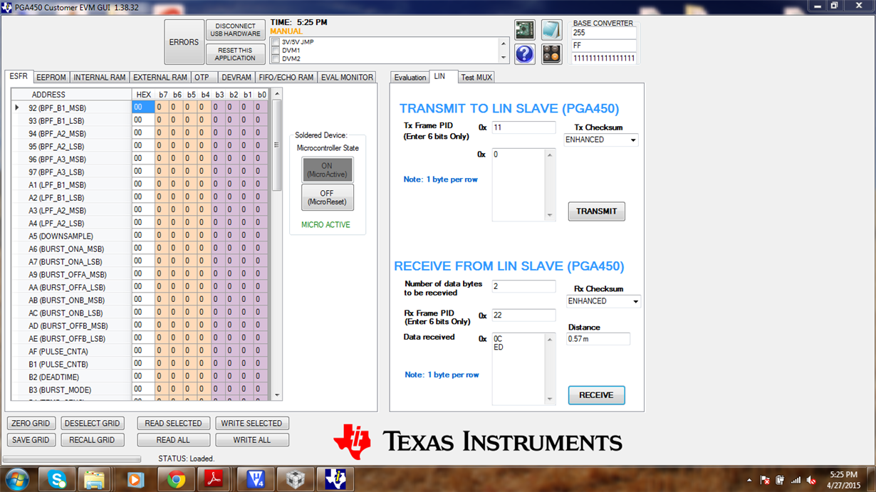
    Value for Short Distance -Data received 0x0CEE,Distance =0.57m.

    Is there any particular settings in EVM.

        i have included the images of both Short and Long distance settings in GUI for LIN communication.

    Thank you,

    Sanath Rai

  • Sanath,

    There are two methods you can use to correct this problem:

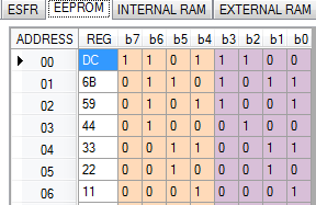
    1. You can observe whether the no-object / empty setup FIFO reading exceeds the EEPROM stored thresholds at the long and short distances constant readings of 0.94m and 0.57m respectively. You can try increasing the EEPROM threshold levels to optimize the trigger for your setup. This process is depicted on page 4 of the demonstration write-up you are referencing.

    2. When using the LIN  tab of the GUI, the drive settings transmitted to the LIN slave are called from the “PGA450_isrs.c” firmware file. These values are fixed, thus the firmware must be modified, and a new .HEX file must be generated/loaded into the PGA450-Q1 if you are attempting to adjust the FIFO waveform, while keeping the original EEPROM thresholds.

    For the following example, I have placed a box approximately 82 inches from the transducer, and use method #2 to correct the constant LIN received distance problem.

    Here is how I modified the snippet of code needing changes (also showing EEPROM threshold settings):

    I was able to optimize the firmware settings after adjusting the values on the “Evaluation” tab via SPI to achieve a reasonable reading. Figure 1 shows the SPI based Evaluation tab’s graph optimized for measuring the box 82 inches away before I modified the firmware. After SPI optimization and modifying/reloading the firmware for LIN, Figure 2 shows the near equivalent FIFO graph as “Invoked through LIN”. When this Invoke through LIN” checkbox is checked, the evaluation tab will send the TX command entered on the LIN tab, then put the micro in reset to read and plot the FIFO data.  This is basically a quicker way to test the PGA450’s firmware, instead of having to manually put the chip in reset and export the data to excel from the FIFO tab. Since the box is placed more than 1.5 meters away from the transducer, a long distance burst is required. Figure 3 shows the result of a long distance burst in the LIN tab when using the modified firmware (correct result).

    Figure 1. SPI Evaluation Tab Optimized for Box

    Figure 2. Invoke through LIN equivalent to SPI

    (post firmware optimization)

    Figure 3. Long Distance LIN Tab TX/RX

  • Hello Akeem,

    Thank you for the response.

    we are testing all the aspects you have given.

    i want to  know can we communicate with PGA450Q1 using SCI buffered mode instead of LIN using the same firmware by changing the LIN_SCI register value or do we need to change anything more on firmware side  or any changes in hardware side (EVM board).

    Thank you,

    Sanath Rai

  • Sanath,
    If are using SCI buffered mode, also take into consideration the DATA_CNT register. The minimum value for DATA_CNT in SCI buffered mode is 2; that is, when the device is configured to operate in SCI buffered mode, the device can receive or transmit a minimum of 2 bytes.
    There are no hardware changes necessary when using SCI buffered mode.
    See datasheet pages 45-46 for additional firmware details on SCI Buffered Mode.