This thread has been locked.

If you have a related question, please click the "Ask a related question" button in the top right corner. The newly created question will be automatically linked to this question.

TPS65381-Q1 SDN6 Extra Pulse

Other Parts Discussed in Thread: TMS570LS3137, TPS65381-Q1

Hi all,


We have a design using a TMS570LS3137 processor with a TPS65381-Q1 PSU chip.

The design is working, but there is audible noise from the PSU circuitry, which gets louder with increased load.

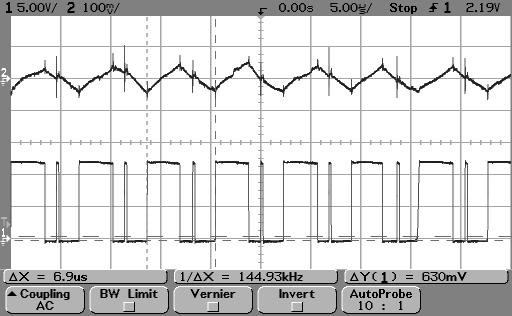
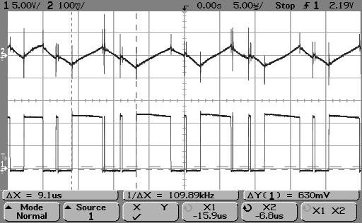
Investigation of the SDN6 switching waveform shows an extra pulse which we can't explain.

These traces were captured under the following conditions: VBat = 12V, load applied directly to VDD6 using load box, processor held in reset. Channel 1 shows the ripple on VDD6, channel 2 shows the switching of SDN6.

With 100mA load on VDD6:

With 1A load on VDD6:

With 12V in and 6V out, the duty cycle should be 50%, which it is, apart from that extra pulse in the middle of each off period.

I found similar graphs in two other threads on these forums, here and here, but neither of them actually addressed the issue.

is anybody able to explain why that extra pulse is there, and what we need to do to remove it?

Regards,

Graeme

  • Hi Graeme,

    This was explained on a similiar E2E post here:  

    The VDD6 is a hysteretic converter so it is not out of the ordinary to see switching cycles like this in this control architecture.  The switch turns on only with the internal clock signal, but the switch will turn off based on the feedback pin voltage sense.  In a lot of the literature you will see the operation called pseudo harmonic.  Also, when you add scope probes to the switch node the noise may be couple or made worse which also can trigger the comparitor in the feedback circuit to shut the switch off when it otherwise wouldn't.  Attached in the other E2E is a plot we took which is similiar to your plots with the explaination of the behavior.

    We haven't heard audible noise in the past from this.  Make sure you are using the proper VDD6 output capacitance (effective capacitance, including tollerance and voltage de-rating) from 22uF to 44uF.  These should be ceramic capacitors, pay close attention to the de-rating of your specific capacitor(s) as we have seen some 16V rated capacitors de-rate to about 8uF at 6V which is the operating point of VDD6.  Also, since this is a hysteretic converter a controlled ESR of 100 to 300mOhm is needed to operate properly.  There is a simplified formula in the Rev C datasheet in the VDD6 applicaiton section that will help balance the ESR, L and C.  Just make sure to round up to 100mOhm even if the calculation comes out a little low, this is due to the simplified nature of the formula.   With these you should get to the most stable operation.  It may be impossible to remove all the switching noise spikes that cause some of these pulses though.

    Best Regards,

    Scott


  • Hi Scott,

    Thanks for the quick response!

    That explanation makes sense, although I can't view that other thread - something about no access, maybe just a dodgy link? - which might explain why I didn't find it myself!

    It may well be that our audible noise is caused by something else - it's just that we haven't seen a switching waveform like that before so we thought that might be causing it.

    I'm fairly sure we have met the requirements for VDD6 output ESR, L and C, and the layout is good, so we will investigate a bit further.

    We did notice that with a stable load applied to VDD6 for our testing yesterday, the noise was much quieter than in normal operation. Could it be possible that when all the associated circuitry is running, the varying load causes stability issues? The processor current demand does seem to be quite dynamic, and we have various other transient demands on the various PSU outputs.

    Regards,

    Graeme