This thread has been locked.

If you have a related question, please click the "Ask a related question" button in the top right corner. The newly created question will be automatically linked to this question.

PGA450-Q1 EVM test ploblem

Other Parts Discussed in Thread: PGA450-Q1, PGA450Q1EVM

Hello

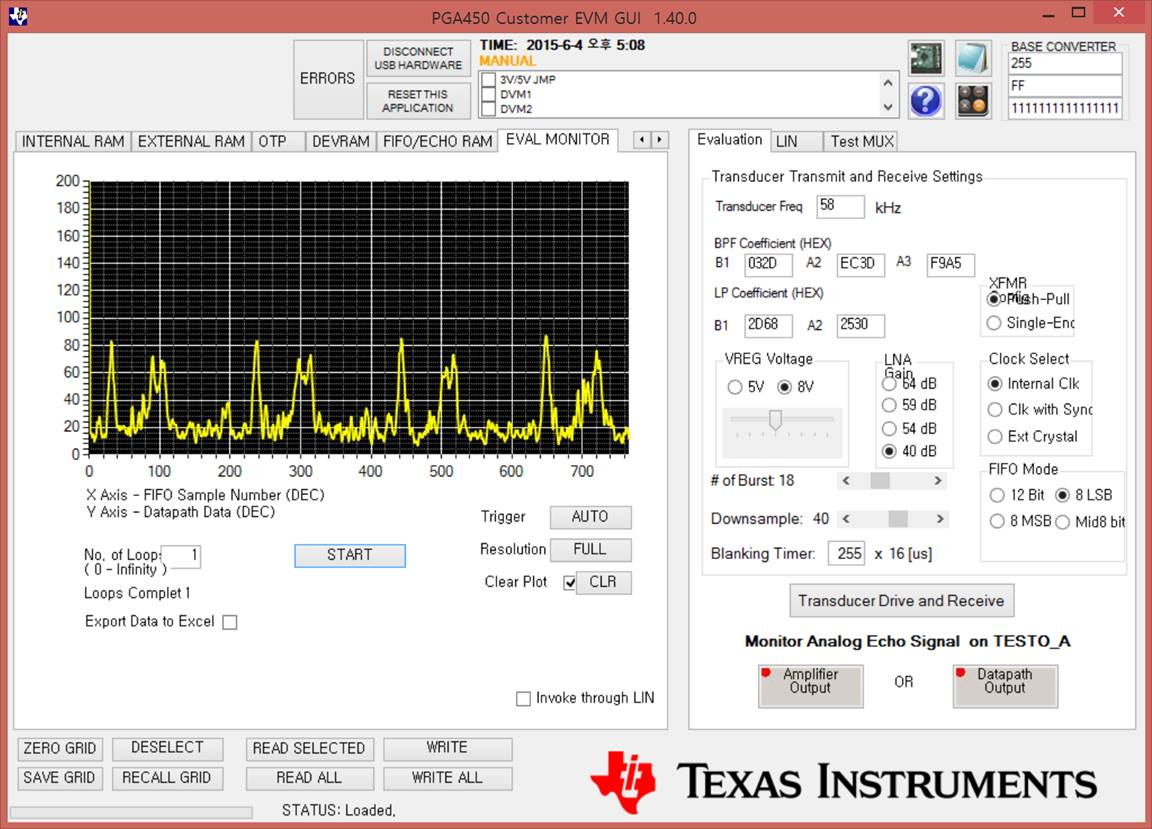
I have been testing the PGA450 EVM using "PGA450 Customer EVM GUI 1.40.0"


ButI think it is no normal waveform.


I have attached the picture below.

Please Check it~ Thanks~

  • Anthony,

    The appropriate applications engineer has been notified of your question and will respond accordingly.

    Regards,
    Eric Hackett
  • Dear Eric
    please check it.
    I appreciate your help.
    Thank you!!
  • Anthony,
    Can you capture a few additional waveforms to help me better understand your issue?
    I need you to capture:
    • a screen capture of the GUI after changing the Blanking Timer value '0'.
    • an oscilloscope screen capture probing:
    ○ XFMR Return
    ○ OUTA
    ○ OUTB
    ○ VREG

    Is the error consistent/repeatable?
    What type of lab environment are you evaluating the PGA450-Q1 in?
    Have you attempted to reduce the FIFO MODE to 'Mid8 Bit'?
    Is object detection possible at all, or do you only see the saturated noise floor?
    Is JP4 shunt jumped instead of JP5?

    Thanks,
  • Dear Akeem

    Thank you for your reply.

    • a screen capture of the GUI after changing the Blanking Timer value '0'.

    • an oscilloscope screen capture probing:
    ○ XFMR Return


    ○ OUTA


    ○ OUTB


    ○ VREG

    Is the error consistent/repeatable?

    ==>Error is Consistent

    What type of lab environment are you evaluating the PGA450-Q1 in?

    ==> PGA450 Customer EVM GUI 1.40.0

    Have you attempted to reduce the FIFO MODE to 'Mid8 Bit'?

    ==>There is no difference in that noise is output

    Is JP4 shunt jumped instead of JP5?

    ==>Noise is continually occured only output level is different.

    Plese check it.

    Thanks,

  • Sorry, I re-attach the Waveform

    • a screen capture of the GUI after changing the Blanking Timer value '0'.

    • an oscilloscope screen capture probing:
    ○ XFMR Return

    ○ OUTA

    ○ OUTB

    ○ VREG

    Thanks,

  • Dear Akeem

    Thank you for your help.

    Please Check it.

    Thank you!!

  • Anthony,

    Your GUI screen capture still shows the Blanking Timer value at 255. Please double-check.


    Based on your oscilloscope screen captures, the XFMR Return indicates that the driving voltage required to excite the transducer is too low. Your peak-to-peak value on the secondary side of the transformer is only 20Vp-p, but should be greater than 100Vp-p if you are using the default transducer-transformer combination. This weak secondary side voltage is a result of the low VREG voltage averaging 700mV. Although, I would also ask that you ensure the oscilloscope probe you are using is set at an attenuation of "1x" and not "10x". Please use a multimeter to confirm VREG is actually averaging 7V instead of 700mV. If the probe was set at "10x" for your measurements, then all measurements are actually correct.

    The following is an example of a working oscilloscope and GUI screen capture, when measuring an object 2.15m away while bursting 6 pulses at a Blanking Timer value of '0' and VREG=5V:

    Your noise floor changes based on the FIFO Mode selected, which is what we expect. The response to "What type of lab environment are you evaluating the PGA450-Q1 in?" may need elaboration, as your noise floor appears to be very high at the FIFO Mode of 8LSB. You may be working in a physical lab environment which is noisy, and interfering with the performance of the ultrasonic Tx/Rx. You could try performing your tests in a different setting, or use a 12V battery to power the PGA450Q1EVM in a vacant/clear space outside.

    Refer to the Application Note: Optimizing Performance of the PGA450-Q1 to fine-tune performance in software.

  • Anthony,
    How far from the sensor is the object that you are trying to detect?