This thread has been locked.

If you have a related question, please click the "Ask a related question" button in the top right corner. The newly created question will be automatically linked to this question.

TPS79801-Q1 over heat issue

Hola,

We have a serious over heat issue about TPS79801-Q1, 50% production error rate by TPS79801-Q1 over heat that causes MSP430 internal flash data error.

After analysis and we found the power pad(thermal pad) solder paste is not good enough and it will causes device over heat and increased leakage current!

Does this thermal pad connected to the GND pin internally?why it causes increased leakage current by poor solder paste?

And I have measured the current at the output side from TPS79801-Q1, when device is at normal temperature and the output current is about 20mA,

but when I measured the over heat device and the output current is about 120mA!Is this caused by poor solder from thermal pad?

  • Hola,
    Can someone help to reply this serious urgent issue ASAP?!
  • Hi Jacky,

    The thermal pad of this device is connected to GND through large resistance.
    If the thermal pad is not soldered properly, thermal problem would rise, but not the leakage current.

    Would you please tell me the device working condition? VIN range, VOUT you set, working ambient temperature and the load condition (MSP430 only?).
    Have you check if there is any shortage occurred in the board? As you measured 120mA, current limit should be triggered, could you please get a waveform of VIN, VOUT and IOUT?

    Best regards,
    Jason Liu
  • Hola Jason,

    Thank you for your prompt reply, after analysis and the follows is MSP430 & TPS79801 abnormal symptom:

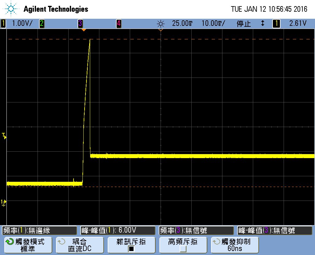
    1. TPS79801 can’t regular output voltage on 3.3V…see below figure ( Vin 12V ~ 16V & Vout is 3.3V).


    2. Continue item(1.) we found the over heat issue on TPS79801 due to abnormal current happened ( 8mA --> 100mA+), at beginning, we assumed that the thermal pad soldering issue but I can’t duplicated it by thermal pad floating.

    3. MSP430 work on 3.3V, we found some MSP430 was burned and the leakage current happened about 40mA / some MSP430 can worked fail even the programmer report it pass.


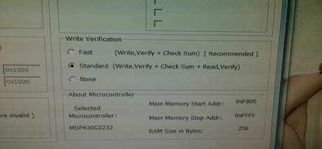
    About the above figure, if we modify the programmer set from Fast to Standard, we can found some MSP430 will be write failed and need re-program, we don’t know what’s different of it!

    4. MSP430 failed units 159pcs/300pcs at production line --> test by set “ Fast “ first and read back checksum verify again.

    Test items

    Test ( setting is Fast)

    Check Sum OK

    Check Sum NG

    Press MENU button no signal

    44

    28

    16

    Press Reset button no power on

    55

    49

    6

    Low current

    60

    15

    55

  • Hi Jacky,

    Does this problem occur on every boards? Have you found any shortage at the device output?
    Has customer performed the A-B-A test? Replaced bad device with good ones?

    As the the phenomenon you described, I suppose current limit of this device is already triggered and the output voltage should be as low as 0V. Could you please obtain the waveform of VIN, VOUT, IOUT of the failed device/board? And would you please send me the schematic of this power section? If it is confidential, please send me directly through the email address below.

    Best regards,
    Jason Liu
  • Hola Jason,

    1. 70pcs failed on CheckSun verified, 430pcs --> fail rate 20%, not happened on every board.
    2. No any HW issue on this issue.
    3. Yes, we did it, and it is 430 depended
    4. Please see below schematic:
  • Hi Jacky,

    I think I find the cause for the thermal and large output current issues. (I am sorry I didn't notice there is the voltage waveform in the previous post. )
    In the waveform, as you said it's the output voltage, there is a voltage spike, and the maximum value is about 6.5V and last for about 4ms. This voltage spike is strong enough to damage the MCU. When MCU is damaged, there would exist one low resistance path from OUT to GND, and that triggered the current limit of TPS79801-Q1, which you could measure the 120mA at the output. And this large current caused the thermal issue.

    Back to the waveform, I doubt whether it is really the output voltage of TPS79801-Q1. There is no output voltage overshoot or spike during different power up / line transient test on my bench test with the same setup with customer's condition.
    Do you know when does this voltage spike occur, during power up, normal working status, or during MCU program burning in?
    Could you please help obtain the waveform of VIN, VOUT, IOUT of the failed device/board without MCU?

    Best regards,
    Jason
  • Hola Jason,

    Thank you very so much.