This thread has been locked.

If you have a related question, please click the "Ask a related question" button in the top right corner. The newly created question will be automatically linked to this question.

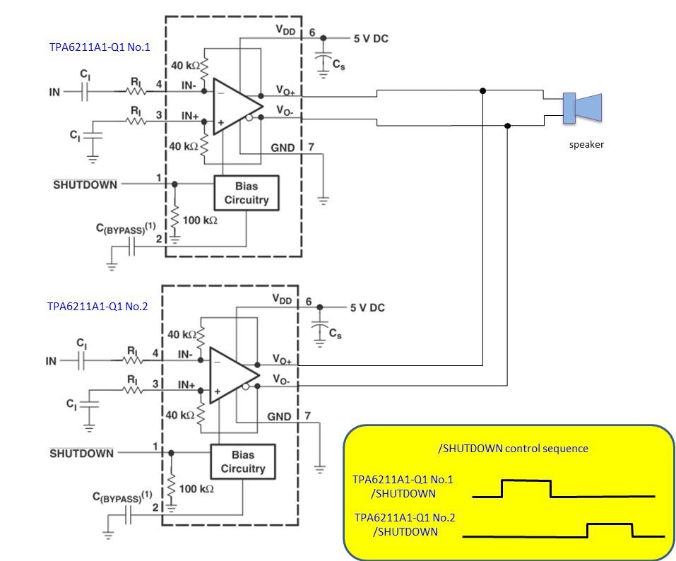
TPA2005D1-Q1 and TPA6211A1-Q1 Connect two amplifier and one speaker

Other Parts Discussed in Thread: TPA6211A1-Q1, TPA2005D1-Q1, TPA6211A1, TPA2005D1

Hello,


Customer wants to use TPA2005D1-Q1 and TPA6211A1-Q1 as following figure, and control each /SHUTDOWN as following.


Please answer following our concern.


Q1:

TPA2005D1-Q1 datasheet has following specification.

Output impedance is 1kohm typical and not so high and not high impedance.

Also TPA6211A1-Q1 has 1uF load of TPA2005D1-Q1 LC filter.


Are their any problem when TPA2005D1-Q1 is shut down and TPA6211A1-Q1 drives speaker?


Q2:

TPA6211A1-Q1 datasheet doesn’t have any explanation about Vo+/- state when /SHUTDOWN is Low.


Does Vo+/- of TPA6211A1-Q1 goes high impedance when /SHTUDOWN is Low?

And are their any problem when TPA6211A1-Q1 is shut down and TPA2005D1-Q1 drives speaker?


Q3:

Please advise if above usage has any concern or OK.


Best Regards.

  • I need a little time to look into this use case.  I will give you an answer next week.

    Thanks,

    -Clancy

  • Hello Clancy-san,

    Thank you for your reply.

    Customer needs answer as soon as possible.

    So please give me cooperation to us.

    Best Regards.

  • Hello Clancy-san,

    If above usage has problem please advise the method to connect two amplifier with one speaker.

    Best Regards.

  • Toshio,

    There is an issue with the TPA6211A1 driving the 1uF capacitor. It causes instability. Does the customer need the LC reconstruction filter, or could they use a ferrite bead filter?

    I have a short report that I will share with you tomorrow that shows the instability.

    Thanks,

    -Clancy
  • Hello Clancy-san,

    Thank you for your bench result.

    I am asking customer if they can use ferrite bead filter but it seems difficult to use ferrite bead filter because LC filter may need to pass the radiation test.

    Please send the report that shows the instability.

    Best Regards.

  • Hello Clancy-san,


    Customer must use LC filter to pass radiation test.


    Please send the report that shows the instability when using TPA6211A1-Q1, TPA2005D1-Q1 and LC filter(C=1uF).


    Also, please advise following use case is OK or there is some issue.


    Best Regards.

  • Hello Clancy-san,


    Please answer above my question.

    Customer has to fix their design soon.


    Best Regards.

  • Hello Clancy-san,

    Please respond my question.

    Best Regards.
  • I've attached the report with the test results with the TPA6211A1 and the 1uF capacitance.  When I tested output capacitors on the order of 1-5nF, there were no instability problems.  So the customer still could implement a ferrite bead filter.

    TPA2005D1 and TPA6211A1.pptx

  • Hello Clancy-san,


    Thank you the test results.


    Q1:

    Center of output sine waveform of your test report on page 4 is 0V.

    Please advise how did you measure OUT+ and OUT- waveform.

    Did you use differential probe?


    Q2:

    I tested TPA6211A1 output waveform using TPA6211A1 and TPA2005D1 EVM and LC filter.

    Attached is OUT+ and OUT– waveform from GND and could not observe unstable output for all 3 cases.

    TPA6211A1 1uF Load.pptx 


    Could you please re-check your test results?


    Best Regards.

  • I will double check the test results. On page 4, I believe that the OUTx waveform was AC coupled.
  • Hello Clancy-san,


    Thank you for your reply.


    I could not reproduce TPA6211A1-Q1 unstable output with 1uF load.

    Please double check your test results and explain unstable mechanism if it is true.


    Best Regards.

  • Hello Clancy-san,


    Customer has to fix design as soon as possible.

    Could you please let me known double check results of TPA6211A1-Q1 output with 1uF load.


    Best Regards.

  • Toshio,

    Thank you for double checking my results. I repeated the test in the lab and did not see the unstable behavior like I did last time. Possibly the oscilloscope I used previously had an issue. I apologize for the incorrect results.

    It looks like this set-up should work out, as long as both devices are powered at the same time and that only one will be in active mode at a time.

    As discussed previously, a signal will be observable on the input pins of the TPA6211A1 when a signal is applied to the TPA6211A1 output pins. This means that both the amplifiers should be driven independently.

    Thanks,

    -Clancy
  • Hello Clancy-san,


    Thank you for your re-test results.


    I reported your result to customer with notice of both devices must be powered and output signal will be observed at disabled TPA6211A1 input terminal.


    Best Regards.

  • Hello Clancy-san


    Please answer additional following question from customer.


    Please refer figure that I posted Jul 1, 2016 (connect TPA2005D1-Q1 and TPA6211A1-Q1 to one speaker).

    Please advise what will happen when both amplifier drives speaker at the same time accidently.


    For example…

    -There is a risk of TPA2005D1-Q1 and/or TPA6211A1-Q1 will be damaged.

    -Both amplifier continue to drive speaker but amplifier will not be damaged.

    -TPA2005D1-Q1 will shut down working short circuit detection and both amplifier will not be damaged.


    Best Regards.

  • Ushikubo-san,

    I would not expect this to lead to damage, but I recommend that thorough testing on your system be done first to verify that.  The short circuit protection of the TPA2005D1 and the thermal protection of both devices should protect against damage to the parts.

    Note that the speaker might not react well to this condition either.  It will certainly cause audible noise.

    Thanks,

    -Clancy

  • Hello Clancy-san,


    Thank you for your answer.


    I tried to test the behavior when both amplifier drive the speaker at the same time.

    Please refer attached file.

     TPA6211A1 and TPA2005D1.pptx

    I used the different sinewave for each amplifier input.

    From the input waveform of TPA6211 and SP- and TPA2005 VO- waveform, speaker is driven by TPA6211.

    TPA2005 is trying to drive 8ms interval but it stopped(may be shutdown).

    From my understanding, TPA2005 should recover from shutdown only when /SHUTDOWN terminal is toggled or power is recycled. But it seems that TPA2005D1 recover automatically after 8ms.

    (When I short VO terminal to GND, TPA2005D1 is shutdown and doesn’t recover automatically.)


    Could you explain above behavior why TPA2005D1 recover from shutdown after 8ms?


    Best Regards.

  • There are two different protection mechanisms on the TPA2005D1-Q1:

    1. short-circuit protection:  This is designed to detect shorts to battery or ground. It works by monitoring the current through the output drivers and will turn off the device when a short circuit occurs. To recover from this, it is necessary to toggle the shutdown pin or power cycle.

    2. Thermal shutdown: This will turn off the device when the internal temperature sensor exceeds a certain value.  It will then attempt to recover once the temperature is lowered. During a soft short, this might trigger instead of the short-circuit protection depending on if the short-circuit current threshold is reached.

    In this case, it looks like the short-circuit current threshold is not reached since it isn't a direct short to battery or ground.  Instead, the amplifiers fighting each other causes the TPA2005D1-Q1 to enter thermal shutdown first. Once the temperature lowers, the TPA2005D1-Q1 starts again.

    Thanks,

    -Clancy

  • Hello Clancy-san,


    Thank you very much for your answer.


    I understand that TPA2005D1-Q1 is entering thermal shutdown.

    I tested amplifier fighting for some TPA6211A1-Q1 input amplitude, but TPA2005D1-Q1 switching interval (recovery time from shutdown) is 8ms constant. (Please refer page 2 of attached file.)

    TPA6211A1 and TPA2005D1_20161121.pptx


    Could you please explain the reason why switching interval is 8ms constant. (For example thermal shutdown has some internal timer to determine minimum time to recover.)


    Best Regards.

  • Hello Calancy-san,

    Please answer my question.

    Best Regards.
  • Ushikubo-san,

    Thank you for your patience. We had the Thanksgiving holiday last week, so I was out of the office. It looks like the TPA2005 is waiting about 8ms and then is attempting to start again.

    This could either because it is taking about 8ms for the device to cool past the thermal shutdown point (plus hysteresis), or it could be because there is an 8ms timer after which the device will attempt to restart. One way to test this theory will be to change the environmental conditions and see if the 8ms interval changes. For instance, you could use a fan to help cool the device, or use a temperature chamber to change the ambient temperature. 

    Thanks,

    -Clancy

  • Hello Clancy-san,


    Thank you fot your answer.


    I tested changing temperature and TPS2005D1 sample.

    I don’t have chamber so I heated using hot hair drier for Hot tenmperature.

    I used fun for cold condition, and result is follows.


    8ms interval slightly changed between sample-1 and 2, but doesn’t change between Hot and cold.


    Could you ask designer about thermal shutdown recover mechanism of TPA2005D1.

    (If I can explain mechanism of this behavior, I can say that TPA2005D1 thermal shutdown occur and probability of device damage is very low.)


    Best Regards.

  • Hello Clancy-san,

    Thank you for your support.

    Could you respond for my above question?

    Best Regards.
  • Ushikubo-san,

    Thank you for running those tests! They are exactly what I was asking for. Since the period did not vary much between the three tests (ambient, hot air, and fan), then it must be using an internal timer and attempting to turn on every 8ms.

    It would be great if they had a way of detecting if this problem was occurring in their system. That way they can turn off one of the devices in that case.

    Thanks,

    -Clancy
  • Hello Clancy-san,


    Thank you for your reply.


    I think it must be using an internal timer and attempting to turn on every 8ms.

    But I can’t believe that thermal protection is triggering this behavior because VDD current is less than 10mA and package surface is no heated and almost ambient temperature.


    I want to be more clear about explanation of this behavior to explain to customer.

    So I tried to measure Vo current and result is attached file.

    TPA6211A1 and TPA2005D1_20161214.pdf


    I reproduced same phenomenon connecting R Short between filter inductor and GND.

    TPA2005D1 attempted to turn on every 8ms with both 1.1 ohm and 0.6 ohm resistor, and stop switching when output current reached around 800mA.


    According to above results my assumption is that TPA2005D1 stops switching when output current reached around 800mA and retry to start after 8ms.

    And TPA2005D1 latch off when reached following output current.

       Short to 5V: 2.3A

       Short to ground: 2.54A

    (Your answer of another E2E: https://e2e.ti.com/support/applications/automotive/f/26/p/506324/1837420#1837420)


    Could you confirm my assumption is correct or not?


    Best Regards.


  • Hello Clancy-san,


    Could you please reproduce 8ms retry behavior using TPA2005D1 EVM and let me known if result is same with my observation?


    And also please answer above my question.


    Best Regards.

  • Ushikubo-san,

    Thank you for attaching the report. I will re-test this in the lab. When I performed the previous measurements about short circuit detection thresholds I was using a hard short, so it is possible that there was overshoot before the turn-off mechanism kicked in.

    There are situations where the thermal shutdown can occur before the short-circuit detection, but I think that with this part at VCC = 5V, that should not be the case.

    Thanks,

    -Clancy
  • Hello Clancy-san,

    Thank you for your reply.

    Please re-test and let me known your result and mechanism of 8ms.

    Best Regards.
  • Ushikubo-san,

    I retested the short circuit current limit on the TPA2005 and it was the same as in my previous tests, about 2.5A. I even tried adding resistance in the short to slow it down (so that I wasn't measuring an over-shoot).

    Is it possible that the resistance in your tests was slightly lower? Is the power supply current limited?

    Thanks,

    -Clancy