This thread has been locked.

If you have a related question, please click the "Ask a related question" button in the top right corner. The newly created question will be automatically linked to this question.

AFE4400SPO2EVM with NJL5501R

Other Parts Discussed in Thread: AFE4400SPO2EVM, CC2541, AFE4400

Hello,

I'm trying using AFE4400SPO2EVM with reflectance probe - NJL5501R.

I want to see the ADC capture waveform in time domain, but i have no idea

how to set the device configurations.

we use Va = +5V, 10k ohm, and 1muF in bias and transfer circuit. 

We need help how to set the each part of device configuration in AFE4400SPO2EVM GUI.

Thanks!

Best regards,

Dawnny Liao


  • Hello Dawnny,

    What is your application?

    Where on the body is the sensor applied?  Forehead?  Wrist? elsewhere?

    The sensor's location on the body will determine greatly how to setup the AFE4400 and whether a signal can be captured at all.  If signal is not present, you can change the placement of the sensor (place it over an artery), add gain in analog to boost signal, increase LED current settings to increase photon back scattering, etc..

    We can answer more completely, once we have a few more bits of information.

    Best Regards

    Praveen.

  • Hi Praveen,

    The sensor is applied on forefinger.

    We set the LED red current to be 0.4mA, and the LED IR current is 3.0mA.

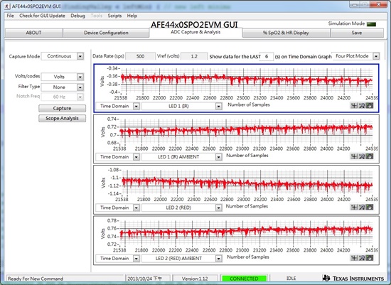
    Here is the ADC capture waveform in time domain, but it seems not correct.

    Is there anything else should I provide? 

    Thank you very much for help!


    Best regards,

    Dawnny.

  • Hello Dawnny,

    We have found it difficult to get PPG signal on the thumb using NJL5501R across multiple subjects.

    The sensor is very sensitive to ambient noise. Any externally picked up noise can dramatically degrade the quality of PPG signal.

    Also the sensor datasheet recommends an optimal distance between finger and the sensor.

    The test subjects are also definitely a concern. Depending on the test subject, the AFE TIA gain, LED current settings need to be modified to get a reasonable PPG signal.

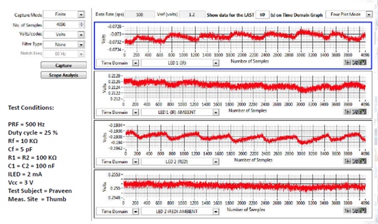
    Please find a sample ADC waveform with the AFE test conditions below with the sensor placed on my thumb.

    Regards

    Praveen.

  • Hello Praveen,

    Is it ok if the data of LED Red/IR are negative?

    Thanks and regards,

    Dawnny.

  • Thinking about the photo-transistor configuration with AC coupling, the internal TIA is configured in a –ve voltage gain amplifier configuration.

    Because of this, the output should always be –ve, except for ambient which could be slightly positive due to offset of the amp.

    So, yes it is ok if the data is negative when using a phototransistor.

  • Hi Praveen

    We have used the NJL5501R part in our design. In the design we have used CC2541 + AFE4400+ NJL part.

    We are reading the data from AFE and sending it over BLE using Btool for the below settings on AFE:

    PRF=500Hz

    Duty cycle = 25%

    Cf=5pF,Rf=10K

    RC value on NJL part used is 100K & 100nF

    we have made a cardboard compartment for NJL5501R around it to prevent the ambient noise effecting the performance.

    There is the ramp in the waveform for RED plotted[decimal vs no. of sample] as attached..
     
    Please let us know the possible reason for this issue.
    Looking forward for your reply
  • Hello Eshak,

    I am unable to view the waveform plots. Can you reattach them?

    What is your measurement site?

    We have seen this issue due to the mechanical setup.

    You may need to affix the sensor to the measurement site (e.g., wrist)


    Regards

    Praveen.


  • Hi Praveen


    I have a one query on waveform captured in AFE4400EVK kit with the TI probe.

    I have captured the IN_N(yellow ) & IN_P (Green) waveform at receiving side of AFE with default EVK settings (PRP:500Hz, LED current: 3.9mA).


    Please let me know whether it is possible to understand from the waveform, where the photodiode outputs the RED,IR, RED ambient & IR ambient.

  • Hello Eshak,

    You will need a reference signal like ADC_RDY to identify the RED, RED ambient, IR and IR ambient phases from the photodiode outputs.

    With EVM settings of 500Hz PRF and 25% duty cycle, from ADC_RDY signal, the output of the photodiode for the first 500us will correspond to Red ambient . The second 500us will correspond to IR, the third 500us correspond to IR Ambient and the last 500us correspond to Red and the cycle repeats every PRP (2ms).


    Regards

    Praveen.

  • Hi Praveen


    Thanks for the reply.

    Please confirm whether my understanding is correct in identifying RED, RED amb, IR & IR amb from the IN_P waveform. I have attached the waveform captured (Green:IN_P vs Yellow:ADC_ RDY).

    I have few doubt mentioned below with respect to PPG signals we get on ADC capture tab of the GUI. I have attached the snap shot of ADC capture tab of GUI for your reference in the next chain.

    1. Dicortic notch which is observed in PPG ( in both RED & IR) is on the left side. Usually the typical PPG waveform always shows the dicortic notch on the right side. Why do we get on the left side. Is that a issue?

    2. There is an option for "show data for _ secs" in the ADC capture tab. What  the option does when we set time for 5 secs or 10 secs.Whether that effects the samples (RED & IR) read from AFE.?

    Regards

    B. Eshak

  • Sorry, i have attached the ADC capture snap shot in previous chain.

    Here I have attached the waveform (IN_P vs ADC_RDY).

  • Hello Eshak,

    As I mentioned in my previous post, the sequence after ADC_RDY signal is LED2 Amb, LED1, LED1 Amb, LED2.

    I have posted an explanation why the PPG waveform is reversed in one of my older posts. See link below.

    http://e2e.ti.com/support/applications/high_reliability/f/30/p/276845/966236.aspx#966236

    The option "Show data for __ secs" is used only for display and post processing purposes. This option presents the last X secs (set by the user) of data samples on the waveform plot. All the post processing like scope, FFT and histogram analysis is done on these data samples and not the entire data samples captured.

    For example when data is captured for 10 secs and the option "Show data for _5_ secs" is selected, the scope and FFT analysis is performed on the last 5 sec samples.

    Hope this helps.


    Regards

    Praveen.

  • Thanks for the clarification on the waveforms.

    I have query with respect to mechanical setup for SPO2 components[RED, IR & Photo detector].

    I am selecting a RED+IR(dual emitter) part & Photo diode part separately and want to integrate together and interface to AFE4400. The testing site is finger tip & ear lobe.

    What should i do on the mechanical setup of these components on the best performance of these sensors.I have been searching on the google for a while but i did not get any much information on mechanical design for LEDs+ photo detector.

    Regards

    B. Eshak.

  • Eshak,

    We don't have much experience with the mechanical construction / setup of sensors to provide a definitive recommendation.

    Finger tip and ear lobe are locations ideally suited for transmissive based pulse oximeter measurements. This should completely reduce a whole lot of complexity in your mechanical design since the LEDs and PD are placed on the opposite side of the tissues. You may want to look at finger tip and earlobe pulse oximeter probes to get an idea of the mechanical construction. You can evaluate the finger tip pulse oximeter probe that came with the AFE4400SPO2EVM kit.


    Regards

    Praveen.

  • Hi Praveen

    Thank you

    Going back to AFE4400 EVK Board, I have below queries:

    1. By default the AFE440xSPO2EVM GUI is set for 500Hz or 500 samples per second. Is there any reason for setting to 500Hz?

    2. In ADC capture & analysis Tab of GUI, whether the samples are read through SPI and displayed directly on GUI. Any processing is done on the samples and then displayed on GUI?

    3. What is the minimum number of samples required for calculating %SPO2?

    Regards

    B. Eshak

  • Hello Eshak,

    There was no specific reason to set PRF to 500Hz in the GUI. But in general, higher PRFs are essential to acquire more information from the PPG signal like heart rate variability etc.

    No processing is done on the samples displayed in the ADC capture & analysis tab.

    There are two types of SpO2 measurements: instantaneous SpO2 and average SpO2. For instantaneous SpO2, you need atleast 1 heart beat. Average SpO2, as the name implies, is the SpO2 averaged over certain heart beat intervals (generally 8).


    Regards

    Praveen.

  • Hi Praveen

    Thanks for the clarification

    For Instantaneous SPO2 calculation, I understand that we require at least one heart beat pulse.

    Is there an approximate value for number of samples (RED or IR) required for one heart beat pulse for 500Hz settings.

    Regards

    B. Eshak

  • Hi Praveen

    We are designing Reflectance type of SPO2 in our design.

    From TI Wrist watch have used RED + IR & Photo diode combo for construction. It works fine for SPO2

    Please let us know how there the mechanical construction has been taken care.


    Regards

    B. Eshak

  • Eshak,

    Assuming the min HR you would like to detect is 30 bpm, the number of samples required to detect one heart beat is atleast 1K for 500Hz PRF.


    Regards

    Praveen.

  • Hi Praveen

    Thanks for the reply.

    I have query w.r.t to waveform of NJL5501R you have captured with your thumb and you have posted earlier on 24th Oct. I have attached the image for your reference

    1. Why the waveform of RED & IR are mirroring each other.

    Usually we see the waveforms with TI probe are symmetrical or similar to each other.

    Regards

    B. Eshak

  • Hello Eshak,

    We did not analyze the PPG signals since we were finding it difficult to get consistent signals for the same subject and across subjects even after tweaking R and C in the biasing network. This is one of the main reasons why we do not recommend and support phototransistor based designs with AFE44xx.

    I do not know if this is due to measurement artifact or something inherent in the design due to the combination of biasing network and IR led.

    Sorry I couldn't be of much help there.

    In your design, do you also notice similar PPG waveforms?


    Regards

    Eshak.

  • Hello Praveen

    Thanks for the reply

    In our design also we are getting the same PPG waveform for the same biasing circuit used.

    But at the measurement site for fore finger was placed at 0.5 cm from the sensor.

    I have below queries with respect to internal AFE4400:

    1. What is the relation between :setting the Rf=10k for NJL5501R and Rf=500K for TI probe and input current of photodetector?
    2.Is it possible to measure current from the photodetector?
    3. Why is that when set Rf=10K iam able to see atleast the inconsistent RED & IR waveform in NJL5501R and not able to see that when set for Rf=500K?
    4. when should be the 2nd stage gain be enabled and for what condition should i set the appropriate gain value?
    5. What does that the input full scale current implies to TIA?
    6. Whether the max.differential output voltage of TIA is 1V?
    7. In our design we have used 3V single supply to both Transmit(LED_DRV_SUP,TX_CTRL_SUP) and Receive Power(RX_ANA_SUP,RX_DIG_SUP) rails.Also the Ground is the same.Whether this causes any issue with respect to AFE functionality.?

    Regards

    B. Eshak

  • Hello Eshak,

    I have received your queries about AFE4400.

    I will get back to you by Monday.


    Regards

    Praveen.

  • Hi, Praveen,

    Could you recommendsome reflective spo2 sensor for AFE4400,my measurement site is wrist.

    BR,

    Sort

  • Hello Sort,

    Some of the reflective sensors we have evaluated are

    1. DCM03 - Integrated dual emitter and photodiode
    2. DLED-660/940-LLS-3 Integrated dual emitter and QSB34CGR - Photodiode
    3. SFH7050 - Multi chip package with 3 emitters and photodiode.

    Best regards.

  • Hi, Praveen,

    Thanks for you recommend, I will try them.

    BR,

    Sort