Hi!
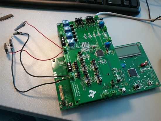
As I said in a previous post, we have purchased the AFE4300EVM-PDK evaluation board and we are using the AFE4300 GUI software to carry out the measurements. The problem is that we are having huge problems when measuring phase in IQ mode. For instance, for a 100 Ohm 1% pure resistor, the measured values for the phase go from 40 to -20 degrees (they greatly vary with the frequency settings). Besides, they also vary with the value of the impedance under test, making impossible any chance of calibration. It seems quite obvious to me that we are committing some aberrant mistake but, so far, we have not been able to find it out. I attach below a photo of our hardware setting. Nothing (jumpers, potentiometers, switches) has been modified since we got the board.
Now I shall describe the soft (AFE4300 GUI) settings.
Global settings: clock 1 MHz (supposed to be internally generated), Internal Vref 1.7 V active, and chip enabled
Weight scale control: disabled
BCM controls: + tension dial to VSENS1 and - to VSENS0. IOUT0 connected to FB0 and IOUT1 to FB1 (at this point, I should ask the upper green connector (J36) contains both IOUT0 and IOUT1 and the lower one VSENS0 and VSENS1, right??). BCM, DAC and IQ are on. (Reference resistors, in case we wanted to use them, are already placed on the board, aren't they??)
ADC controls: BCM AFE I selected for I measurements (BCM AFE Q for Q measurement). ADC is on and 64 SPS.
And these are our settings. Then we measure via the ADC capture & analysis both I and Q components separately. This way we get both codes for a 100 Ohm 1% resistor. Afterwards, we repeat the same process but replacing the previous resistor with a 220 Ohm 1% pure resistor (rest of the hardware remains the same). This way we obtain the codes of I and Q components for the second resistor. Nevertheless, in spite of using the same frequency for both measurements, we obtain phase values completely different (32º and 6º). In this case, calibration is completely impossible, and what is more, these results suggest a clear mistake either of the hard or the soft settings.
We are now making further investigations to find out what the problem is, but any help would be greatly appreciated.
Thanks in advance!
Best regards


