This thread has been locked.

If you have a related question, please click the "Ask a related question" button in the top right corner. The newly created question will be automatically linked to this question.

AFE4490 SPI communication

Other Parts Discussed in Thread: AFE4490, AFE4400, MSP430F5529, ENERGIA, MSP430FR5969

Hello,

 im trying to communicate with an AFE4490 via SPI. For now my setup looks like this: i removed the Resistors R29, R31, R33 and R35 on the EVB and attached cables to connect them to my uC. I tried it with an Bluegiga BLE112 and now with an Arduino Uno. No success so far. The only feedback i got, was a short blinking of the Red LED when doing a Soft-Reset by seting the D3 Bit in CONTROL0 Register high. when I perform that in a loop, the LED  glows, but not very bright. But writing in other Registers seems to fail. Im trying to set all registers to the default values exported from the EVB GUI. So timing and LED current etc should be fine. But nothing happens. Reading Registers returns 0. These are the results i get with an SPI configuration with SPIMode = 1( CPOL = 0, CPHA = 1) , Bitorder: MSB First. Other configurations failed. Clock is 4MHz.

So my Questions are:

1. is my output Voltage of the Arduino Uno of 5V too high for the SPI communication with the AFE? I think in the datasheet, the logic high input voltage is named with 0.75 * RX_DIG_SUP whitch would on the EVB be ca. 2,5V.

2.  Are my SPI configurations correct? (SPIMode, Bitorder, Clock)

3. Do I write or read the Registers wrong? Here the Code(Arduino):

void AFE4400::SPIWriteReg(byte regAddress, uint32_t regValue){
  byte temp_byte = 0;
  digitalWrite(chipSelectPin, LOW);
  SPI.transfer(regAddress & 0xFF); 
  temp_byte = regValue >> 16;
  SPI.transfer(temp_byte & 0xFF); 
  temp_byte = regValue >> 8;
  SPI.transfer(temp_byte & 0xFF);
  temp_byte = regValue;
  SPI.transfer(temp_byte & 0xFF);
  digitalWrite(chipSelectPin, HIGH);
}

and for reading:

uint32_t AFE4400::SPIReadReg(byte regAddress){
byte temp_byte = 0;
uint32_t reg_value = 0;
// enable reading from registers
SPIEnableRead();
digitalWrite(chipSelectPin, LOW);
SPI.transfer(regAddress);
// get first byte
temp_byte = SPI.transfer(0x00);
reg_value = temp_byte << 16;
// get second byte
temp_byte = SPI.transfer(0x00);
reg_value = temp_byte << 8;
// get last byte
temp_byte = SPI.transfer(0x00);
digitalWrite(chipSelectPin, HIGH);
// disable reading from registers
SPIDisableRead();
return reg_value;
}
void AFE4400::SPIEnableRead() {
  SPIWriteReg(CONTROL0, 0x01);
  delay(1);
}

And why ist the LED glowing when doing the soft reset? Do I need to attach more pins to my uC? Things like the !Reset are high anyway by default on the EVM right?

 I hope you can help me, because Im running out of ideas what could be wrong.

 Regards  Marius

  • Hello Marius,

    I have received the issues you have with AFE4490. I will go over the issues and get back to you as soon as possible.

    Regards

    Praveen.

  • Hello Marius,

    To answer your questions:

    1. you may need a logic level converter between the AFE4490EVM and the Arduino board.
    Refer to the following post: http://e2e.ti.com/support/applications/high_reliability/f/30/t/330348.aspx

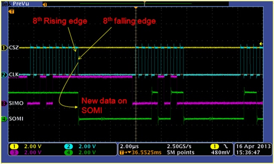
    2. Your SPI configuration seems to be correct but it will be better if you can check your SPI timing waveforms.
    Here is a sample SPI timing waveform.

    3. Your SPI read register function is incorrect. During each byte SPI transfer, you were overwriting the reg_value with the shifted temp_byte. Here is the updated SPI read register function.

    uint32_t AFE4400::SPIReadReg(byte regAddress){
    byte temp_byte = 0;
    uint32_t reg_value = 0;
    // enable reading from registers
    SPIEnableRead();
    digitalWrite(chipSelectPin, LOW);
    SPI.transfer(regAddress);
    // get first byte
    temp_byte = SPI.transfer(0x00);
    reg_value = (temp_byte << 16);
    // get second byte
    temp_byte = SPI.transfer(0x00);
    reg_value |= (temp_byte << 8);
    // get last byte
    temp_byte = SPI.transfer(0x00);
    reg_value |= temp_byte;
    digitalWrite(chipSelectPin, HIGH);
    // disable reading from registers
    SPIDisableRead();
    return reg_value; }

    Can you monitor the voltage on the RESET and PDN pins? Are they logic HIGH?
    Also did you short the GND on both the boards?

    Another community member Stella Laksono has interfaced AFE4490EVM with Arduino board.
    You can reach out to her to find out more details on how she made it possible.

  • Hello Praveen,

    thank you for your reply. I checked the voltage on RESET and PND, both are on 3.3V, should be fine. I shorted the GND now and corrected my code. And thank you for your hind with the logic level converter and the link to the post, but it took me some seconds to notice that they are refering on the datasheet of the AFE4400, because the sheets of the 4490 and 4400 differ in the "Logic high input voltage". 

    While waiting for an logic level converter, I'm trying to get it working with a MSP430F5529 Launchpad, which should meet the 3.3V input voltage. Now I'm runnig my Arduino Code with Energia on the MSP430. A short test didnt show any new results.

    Unfortunatly I wasnt able to check the entire timing because of some issue with the oscilloscope and we hope to solve this in the next days. If nothing works out, I have to consider that the AFE was damaged while attaching the wires. Perhaps I will be able to reconnect them to the uC on the EVB, so I can check that. If you have any other ideas, please let me know.

    Regards

    Marius

  • Hello Marius,

    The voltages on BG and TX_REF are a good indicator of the device powering up (after a reset).

    Refer to the following link for details about the status of the AFE after power-up.

    http://e2e.ti.com/support/applications/high_reliability/f/30/p/331294/1157075.aspx#1157075

  • Hello Praveen,

    thank you for your help. It works now with the MSP with 3.3V. I had a small error from porting my Arduino code. Anyway, thank you again for you informations.

    Regards Marius

  • Hello Marius,

    Thanks for the update. Glad to know that you were able to resolve the issue by yourself.

    If there are any questions related to getting AFE44xx family of devices work with Arduino platform posted by other community members, feel free to jump in and provide your expert opinion.


    Best regards

    Praveen.

  • Hi Marius,

    May I know what error you got from porting the Arduino code to the MSP430? I am trying to interface the AFE4400 to the MSP430FR5969 Launchpad and have been unsuccessful, although I am using a Arduino sketch that worked.

    Regards,
    Abhishek G Nair.