This thread has been locked.

If you have a related question, please click the "Ask a related question" button in the top right corner. The newly created question will be automatically linked to this question.

Problem with my circuit.

Other Parts Discussed in Thread: AFE4400, MSP430F5529, AFE4400SPO2EVM, AFE4403

Hello,

I was planning to run the AFE4400 using only 3.3v. For this I changed the source voltages to 3.3 volts. I am using NJL5310R as the sensor.

I have also made few PCB's to test it out.

But the problem occurs when I try to run my HRM code on the board using MSP430F5529 launchpad. (However the same code works perfectly with AFE4400SPO2EVM connected to NJL5310R(board with DB9) provided by TI)

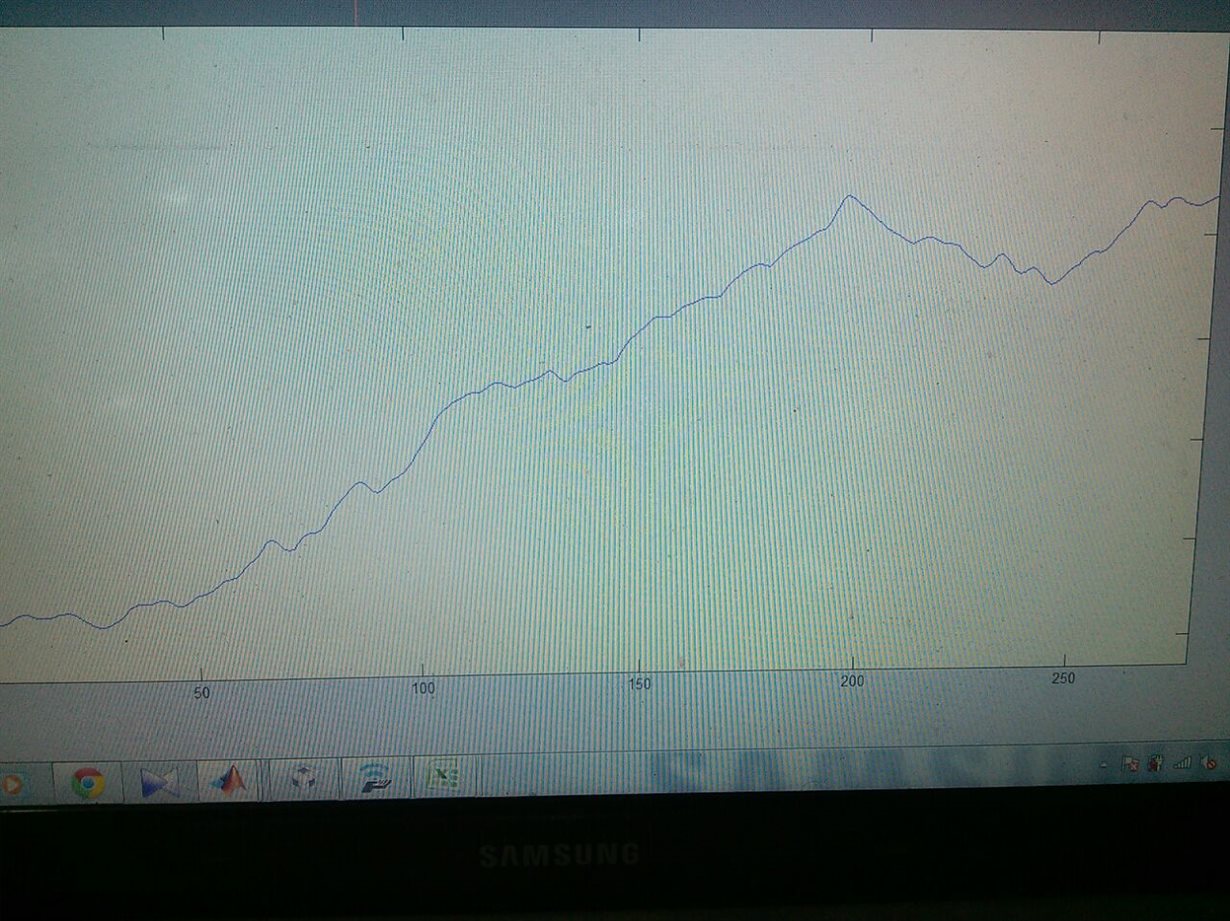
On multiple tests the result was same. I sent the recieved data to matlab for visual analysis and found the data to be vague. I cant seem to find the pulse signal in the data.

My suspects lies with the fact that maybe the circuit that i modified is wrong or the 3.3 need to be highly filtered as done by EVM.

I am attaching the PDF containing my circuit design.
Plz have a look at it and suggest some methods.

PS. the 2 resistor connected by lest of NJL sensor are DNC( Do not Connect)AFE4400EVM_page2.PDF.

  • Hello Atul,

    Looking at the AFE4400 section of the schematics, I did not find anything amiss in your design.
    But then the schematics does not show the DNC parts. Could you provide more info on the DNC parts?

    The 3.3V is fed from the launchpad. Could you check if you supply an external 3.3V to the launchpad, you still encounter the same problem?

    Could you also attach the AFE ADC data?
  • Hello Praveen

    Please find the images related to your queries.

    Here is the image of DNC resistor, the same was not visible in the schematic 


    The schematic is same as given in schematic of AFE4403 EVM(also given below)


    2. yes I have provided the 3.3 volt from the launchpad itself. I will check and confirm using external source. Is there any specific reason you want it to be powered by external suppy?

    3.I am attaching the ADE ADC data of IR led in the image below which I received on MATLAB.

  • Atul,

    Based on the LED configuration, you should be checking the Red LED channel instead of IR LED channel, shouldn't you?
  • Hello,

    There was a typo in the last reply.

    The data is from RED sample. However there is not much of a difference between the data in RED and Data in IR both are extremely unpredictable with no hint of a pulse data..