This thread has been locked.

If you have a related question, please click the "Ask a related question" button in the top right corner. The newly created question will be automatically linked to this question.

SM320F28335-EP: SM320F28335-EP questions

Part Number: SM320F28335-EP

Hi Support,

Let me raise a few questions about SM320F28335-EP.


1.

The DSP device accepts input clock from an external oscillator via XCLKIN pin.
May ask you if the external clock runs through a signal conditioning circuit even when PLL bypass mode is selected?   

2.

I can’t seem to locate worst case values for internal pulls on numerous pins, a good example being boot mode selection pins XA15- XA12. Need to calculate values of external pull-down resistors opposing internal pull-ups as no recommendation was found.


3. I can’t seem to find a package drawing for PTP version. The following link does not seem to help.

http://www.ti.com/product/TMS320F28335/datasheet/mechanical-packaging-and-orderable-information?keyMatch=package drawing delfino&tisearch=Search-EN-Everything

Do you think you could send a hint?

Many thanks in advance,

regards,

Alberto

  • Alberto,
    I will attempt to answer your questions. Please let me know my assumptions are correct.

    1) If using an external 3.3V oscillator, you will need to meet the timing requirements (either with or without PLL). See tables 6-6 and 6-7.
    Additionally, an IBIS simulation can be performed with your oscillator to determine what if any series termination is required for proper signal integrity. An IBIS model is available in the commercial product folder under tools/software.
    2) The strength of the pullup/downs can be seen in the Electrical characteristics table. This is the leakage current for IIL and IIH for pins with pull up/downs enabled. See section 6.3
    3) The packages get automatically added to the end of the datasheet. I just pulled datasheet, and the PTP is present.
    Regards,
    Wade
  • Wade,

    thanks for your feedback.

    Questions 2) and 3) are closed.

    I have more inputs for question 1) and a pretty new questions 4) and 5) on the same topic.

    1) If using an external 3.3V oscillator, you will need to meet the timing requirements (either with or without PLL). See tables 6-6 and 6-7.

    Additionally, an IBIS simulation can be performed with your oscillator to determine what if any series termination is required for proper signal integrity. An IBIS model is available in the commercial product folder under tools/software.

    [Customer ] I have concerns that external oscillator drives internal gates on the DSP silicon die directly when PLL is disabled.

    I personally believe that the DSP device implements a nice clock buffer for the external signal that mitigates potential issues with signal integrity on the board and therefore the concern is irrelevant even for harsh environment applications.

    I would like to receive your comment.

    4) Missing Flash Endurance for M Temperature Material

      Could you please clarify the Flash Endurance specification for M-device?

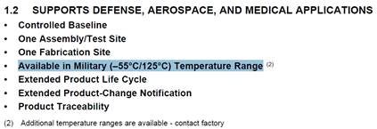
    5) I can’t seem to figure out how to build proper manufacturer part number for the military temperature range.

    Not sure how to combine the -EP acronym with -M dash.

    Do you think you could provide proper manufacturer part number for the military temp range -55C to +125C in the PTP package presented in the –EP datasheet?

    many thanks,

    regards,

    Alberto

  • Alberto,
    1)
    I do not understand the concern on PLL in bypass mode. Could you elaborate this? The vih/vil levels do not change with PLL bypass or not.
    Is there concern for overshoot from signal integrity issue? The IBIS model can help simulate this to set proper termination if required.

    4) I see that our endurance numbers are out of date. Since publishing, the numbers have improved significantly. The numbers can be reference from the commercial device datasheet. The Q range -40 to 125 is rated min of 20,000 cycles. I will have to check with our quality/reliability team to see if values change for -55c operation.

    5) Easiest way to see the orderable part numbers, is to go to the product folder, and select "order now" tab.
    www.ti.com/.../samplebuy

    Regards,
    Wade
  • Hi Wade,

    1) Let me clarify.
    Theory:
    Quality clock is a fundamental prerequisite to a reliable system. Achieving quality clock for a complex clock topology may be no easy task as the risk of non-monotonic edges may be high.
    When the on-chip PLL is used, external oscillator drives a point-to-point trace from oscillator output pin to PLL input ONLY. If external clock is a tad noisy, the noise is NOT propagated to the very complex internal clock net as the PLL recreates a nice and clean clock inside the chip.
    Design description:
    Now, in order to alleviate DSP power dissipation, I intend to use a 150MHz external clock oscillator. When I came up with this solution I was challenged by my superior whose concern is signal integrity of the clock inside the DSP. He says that if PLL is bypassed that the clock oscillator sees a very complex internal clock net and external noise will penetrate all the way to internal gates.
    I, personally, am convinced that the concern above is irrelevant and the system with PLL disabled should be reliable even in harsh environment applications and extreme temperatures.
    Question:
    When the on-chip PLL is disabled , does external oscillator see a point-to-point connection or does it see a complex internal clock net with thousands of gates connected to it?
    Put another way, could you please confirm that external clock signal is ALWAYS BUFFERED/RE-CREATED by means of an internal buffer implemented on the silicon even if PLL is disabled?

    5) Thanks, Closed.

    4) will provide details soon.

    thanks and regards,
    Alberto
  • Alberto,

    You must provide a clean clock, that meets the input requirements in the table.

    cycle time, rise fall times, and duty cycle.

    This also will be including the input Vih/Vil levels.    (you may need to go to forum post to see table below)

    So, as long as your external oscillator is driving the input within the recommended operating conditions. Then device will function as intended.

    The external oscillator will only be driving the input buffer regardless of PLL enable or not.  This buffer will drive the internal circuitry.

    Regards,

    Wade

  • Wade,

    thanks for your feedback.
    Question 1) is closed as well.

    We are only missing question 4), so endurance at -55°C. Can you kindly provide your feedback also for this question?

    Many thanks and best regards,
    Alberto