This thread has been locked.

If you have a related question, please click the "Ask a related question" button in the top right corner. The newly created question will be automatically linked to this question.

OMAPL138B-EP: DSP + ARM working together

Part Number: OMAPL138B-EP
Other Parts Discussed in Thread: OMAPL138

Hi,

I have been given a project  recently related to communication systems. The board that we have decided to  develop the project is LCDK OMAPL138. In this project we need both ARM and DSP chips to work together. The ARM chip will take care of networking and transmitting or receiving the  data, and the DSP chip is going to take care of equalizing, filtering, etc which are computationally intensive.

I have been working with just the DSP chip of this board for quite a long time, but this is the first time I have decided to combine it with ARM chip. After searching about how to make the ARM work with DSP I came across the IPC examples in OMAP StaterWare, which is quite difficult to comprehend! Specially you can't trace back deceleration of some of functions or terms that is used in the IPC example.

The problems I am seeking help for are:

1. how to start a new project in CCS where I can develop a program for both ARM and DSP chip

2. how can I load the program into the chips and do debugging

I would appreciate any hint that could help me progressing this project.

Thanks

  • Please see this E2E post.
    Regards,
    Wade
  • Thanks Wade for your help. I went through the MCSDK User Guide you sent me installed the necessary packages. But my concerns are still remaining.

    I still don't know how to

    1. how to start a new project in CCS where I can develop a program for both ARM and DSP chip

    2. how can I load the program into both chips and do debugging

    Thanks

  • so far I have created to different projects, one for ARM chip and the other for DSP chip on OMAL-l138 LCDK. Both ARM and DSP are running on SYS/BIOS6. To load these program to the board, I have created a target configuration file. and these are the steps I am taking:

    1. Right click on .ccxml -> Launch Selected configuration

    2. Rght click on ARM9 core -> connect to target -> load the program written for ARM core and let it to reach to the beginning of the mian()

    3. Right click on DSP core -> connect to target -> load the program written for DSP core and let it to reach to the beginning of the mian()

    4. run ARM core

    5. run DSP core

    Below you can see the .cfg and file for ARM core. A timer interrupt goes off every 0.5 second and ARM_IPC() sets CHIPSIG2 in order to interrupt DSP core.

    .CFG

    var Defaults = xdc.useModule('xdc.runtime.Defaults');
    var Diags = xdc.useModule('xdc.runtime.Diags');
    var Error = xdc.useModule('xdc.runtime.Error');
    var Log = xdc.useModule('xdc.runtime.Log');
    var LoggerBuf = xdc.useModule('xdc.runtime.LoggerBuf');
    var Main = xdc.useModule('xdc.runtime.Main');
    var SysMin = xdc.useModule('xdc.runtime.SysMin');
    var System = xdc.useModule('xdc.runtime.System');
    var Text = xdc.useModule('xdc.runtime.Text');
    
    var BIOS = xdc.useModule('ti.sysbios.BIOS');
    var Hwi = xdc.useModule('ti.sysbios.hal.Hwi');
    var Task = xdc.useModule('ti.sysbios.knl.Task');
    var Timer = xdc.useModule('ti.sysbios.hal.Timer');
    var Mmu = xdc.useModule('ti.sysbios.family.arm.arm9.Mmu');
    
    
    Defaults.common$.namedModule = false;
    
    
    System.maxAtexitHandlers = 4;
    
    
    Text.isLoaded = false;
    
    
    SysMin.flushAtExit = false;
    
    BIOS.heapSize = 0x0;
    
    /* System stack size (used by ISRs and Swis) */
    Program.stack = 0x400;
    
    /* Circular buffer size for System_printf() */
    SysMin.bufSize = 128;
    
    
    var loggerBufParams = new LoggerBuf.Params();
    
    System.SupportProxy = SysMin;
    
    BIOS.libType = BIOS.LibType_Custom; BIOS.assertsEnabled = true; var timer0Params = new Timer.Params(); timer0Params.instance.name = "timerHandle"; timer0Params.period = 500000; Program.global.timerHandle = Timer.create(1, "&ARM_IPC", timer0Params);

    .C
    //-------------------------------------------------------
    // BIOS header files
    //-------------------------------------------------------
    #include <xdc/std.h>                        //mandatory - have to include first, for BIOS types
    #include <xdc/runtime/System.h>
    #include <ti/sysbios/BIOS.h>                //mandatory - if you call APIs like BIOS_start()
    #include <xdc/cfg/global.h>                 //header file for statically defined objects/handles
    #include <xdc/runtime/Timestamp.h>          //when using Timestamp APIs (TSCL/H), 32bit, 64bit
    
    //-------------------------------------------------------
    // MCSDK-PDK-CSLR Include Files
    //-------------------------------------------------------
    #include <stdio.h>
    #include <ti/csl/soc_OMAPL138.h>
    #include <ti/csl/cslr_syscfg0_OMAPL138.h>
    #include <ti/csl/cslr_tmr.h>
    
    //-------------------------------------------------------
    // PROTOTYPES
    //-------------------------------------------------------
    void hardware_init(void);
    void ARM_IPC(void);
    //-------------------------------------------------------
    // Globals
    //-------------------------------------------------------
    CSL_SyscfgRegsOvly  sys0Regs = (CSL_SyscfgRegsOvly) (CSL_SYSCFG_0_REGS);
    
    //-------------------------------------------------------
    // Main()
    //-------------------------------------------------------
    void main()
    { 
        hardware_init();
    	
        BIOS_start();    /* does not return */
    }
    
    //-----------------------------------------------------------------------------
    // hardware_init()
    //-----------------------------------------------------------------------------
    void hardware_init(void)                        //called by main
    {
    
    // PINMUX SETUP ---------------------------------------------
    
    // Key to be written to enable the pin mux registers for write
        sys0Regs->KICK0R = 0x83e70b13;
        sys0Regs->KICK1R = 0x95A4F1E0;
    
    }
    
    //-----------------------------------------------------------------------------
    // ARM_IPC()
    //-----------------------------------------------------------------------------
    void ARM_IPC(void)
    {
        // IPC -> SYSCFG -> CHIPSIG2
        CSL_FINS(sys0Regs->CHIPSIG, SYSCFG_CHIPSIG_CHIPSIG2, 1);
    }


    Below is the program written for DSP core. after receiving and interrupt from ARM core clears it and blinks an led.


    .CFG
    var Defaults = xdc.useModule('xdc.runtime.Defaults');
    var Diags = xdc.useModule('xdc.runtime.Diags');
    var Error = xdc.useModule('xdc.runtime.Error');
    var Log = xdc.useModule('xdc.runtime.Log');
    var LoggerBuf = xdc.useModule('xdc.runtime.LoggerBuf');
    var Main = xdc.useModule('xdc.runtime.Main');
    var SysMin = xdc.useModule('xdc.runtime.SysMin');
    var System = xdc.useModule('xdc.runtime.System');
    var Text = xdc.useModule('xdc.runtime.Text');
    
    var BIOS = xdc.useModule('ti.sysbios.BIOS');
    var Hwi = xdc.useModule('ti.sysbios.hal.Hwi');
    var Task = xdc.useModule('ti.sysbios.knl.Task');
    
    
    Defaults.common$.namedModule = false;
    
    
    System.maxAtexitHandlers = 4;
    
    
    Text.isLoaded = false;
    
    
    SysMin.flushAtExit = false;
    
    
    BIOS.heapSize = 0x0;
    
    /* System stack size (used by ISRs and Swis) */
    Program.stack = 0x400;
    
    /* Circular buffer size for System_printf() */
    SysMin.bufSize = 128;
    
    
    var loggerBufParams = new LoggerBuf.Params();
    
    System.SupportProxy = SysMin;
    
    
    BIOS.libType = BIOS.LibType_Custom;
    BIOS.assertsEnabled = true;
    var hwi0Params = new Hwi.Params();
    hwi0Params.instance.name = "IPC_Handle";
    hwi0Params.eventId = 5;
    Program.global.IPC_Handle = Hwi.create(10, "&ledToggle", hwi0Params);
    

    .C

    //-------------------------------------------------------
    // BIOS header files
    //-------------------------------------------------------
    #include <xdc/std.h>                        //mandatory - have to include first, for BIOS types
    #include <xdc/runtime/System.h>
    #include <ti/sysbios/BIOS.h>                //mandatory - if you call APIs like BIOS_start()
    #include <xdc/cfg/global.h>                 //header file for statically defined objects/handles
    #include <xdc/runtime/Timestamp.h>          //when using Timestamp APIs (TSCL/H), 32bit, 64bit
    
    //-------------------------------------------------------
    // MCSDK-PDK-CSLR Include Files
    //-------------------------------------------------------
    #include <stdio.h>
    #include <ti/csl/soc_OMAPL138.h>
    #include <ti/csl/cslr_gpio.h>
    #include <ti/csl/cslr_syscfg0_OMAPL138.h>
    #include <ti/csl/cslr_psc_OMAPL138.h>
    #include <ti/csl/cslr_tmr.h>
    
    //-------------------------------------------------------
    // PROTOTYPES
    //-------------------------------------------------------
    void hardware_init(void);
    void ledToggle (void);
    void gpioPowerOn(void);
    
    //-------------------------------------------------------
    // Globals
    //-------------------------------------------------------
    CSL_SyscfgRegsOvly  sys0Regs = (CSL_SyscfgRegsOvly) (CSL_SYSCFG_0_REGS);
    CSL_PscRegsOvly     psc1Regs = (CSL_PscRegsOvly)    (CSL_PSC_1_REGS);
    CSL_GpioRegsOvly    gpioRegs = (CSL_GpioRegsOvly)   (CSL_GPIO_0_REGS);
    
    volatile int16_t i16ToggleCount = 0;
    
    //-------------------------------------------------------
    // Main()
    //-------------------------------------------------------
    void main()
    {
        hardware_init();
    
        BIOS_start();
    }
    
    
    //-----------------------------------------------------------------------------
    // hardware_init()
    //-----------------------------------------------------------------------------
    void hardware_init(void)                        //called by main
    {
    
    // PINMUX SETUP ---------------------------------------------
    
    // Key to be written to enable the pin mux registers for write
        sys0Regs->KICK0R = 0x83e70b13;
        sys0Regs->KICK1R = 0x95A4F1E0;
    
    // Enable the pinmux for the GPIO bank 0 pin 9 (tied to LED on LCDK)
        sys0Regs->PINMUX0 = ((CSL_SYSCFG_PINMUX0_PINMUX0_27_24_GPIO0_9)
                            << (CSL_SYSCFG_PINMUX0_PINMUX0_27_24_SHIFT));
    
    // GPIO SETUP ---------------------------------------------
    
    // First, enable the GPIO Module in the PSC
        gpioPowerOn();
    
    // Configure GPIO0_9 (GPIO0_9_PIN) as an output
        CSL_FINS(gpioRegs->BANK[0].DIR,GPIO_DIR_DIR9,0);
    }
    
    //-----------------------------------------------------------------------------
    // ledToggle() ISR (called by BIOS Hwi, see app.cfg)
    //-----------------------------------------------------------------------------
    void ledToggle(void)                            //called by main
    {
        static Uint32 LED_state = 0;                // used to toggle LED state
    
        // IPC -> SYSCFG -> CLEAR CHIPSIG2
        CSL_FINS(sys0Regs->CHIPSIG_CLR, SYSCFG_CHIPSIG_CLR_CHIPSIG2, 0);
    
        if (LED_state == 1)                         // if LED_state is "1" - ON, turn LED ON via GPIO
        {
            CSL_FINS(gpioRegs->BANK[0].OUT_DATA,GPIO_OUT_DATA_OUT9,1);
        }
        else                                        // LED_state is "0" - OFF, turn LED OFF via GPIO
        {
            CSL_FINS(gpioRegs->BANK[0].OUT_DATA,GPIO_OUT_DATA_OUT9,0);
        }
    
        LED_state ^= 1;                             // toggle LED state
    
        i16ToggleCount += 1;                        // keep track of #toggles
    }
    
    void gpioPowerOn(void)
    {
        volatile Uint32 pscTimeoutCount = 10240u;
        Uint32 temp = 0;
    
    // power on GPIO module in PSC & enable GPIO module
        psc1Regs->MDCTL[CSL_PSC_GPIO] = ((psc1Regs->MDCTL[CSL_PSC_GPIO]
                                            & 0xFFFFFFE0)
                                         | CSL_PSC_MDSTAT_STATE_ENABLE);
    
    // Kick start the Enable command
        temp = psc1Regs->PTCMD;
        temp = ((temp & CSL_PSC_PTCMD_GO0_MASK)
                | (CSL_PSC_PTCMD_GO0_SET << CSL_PSC_PTCMD_GO0_SHIFT));
    
        psc1Regs->PTCMD |= temp;
    
    // Delay enough time for power state transition to occur (status not checked, this is the defn of HOPE)
        while (((psc1Regs->PTSTAT & (CSL_PSC_PTSTAT_GOSTAT0_IN_TRANSITION)) != 0)
            && (pscTimeoutCount>0))
        {
            pscTimeoutCount--;
        }
    
    }


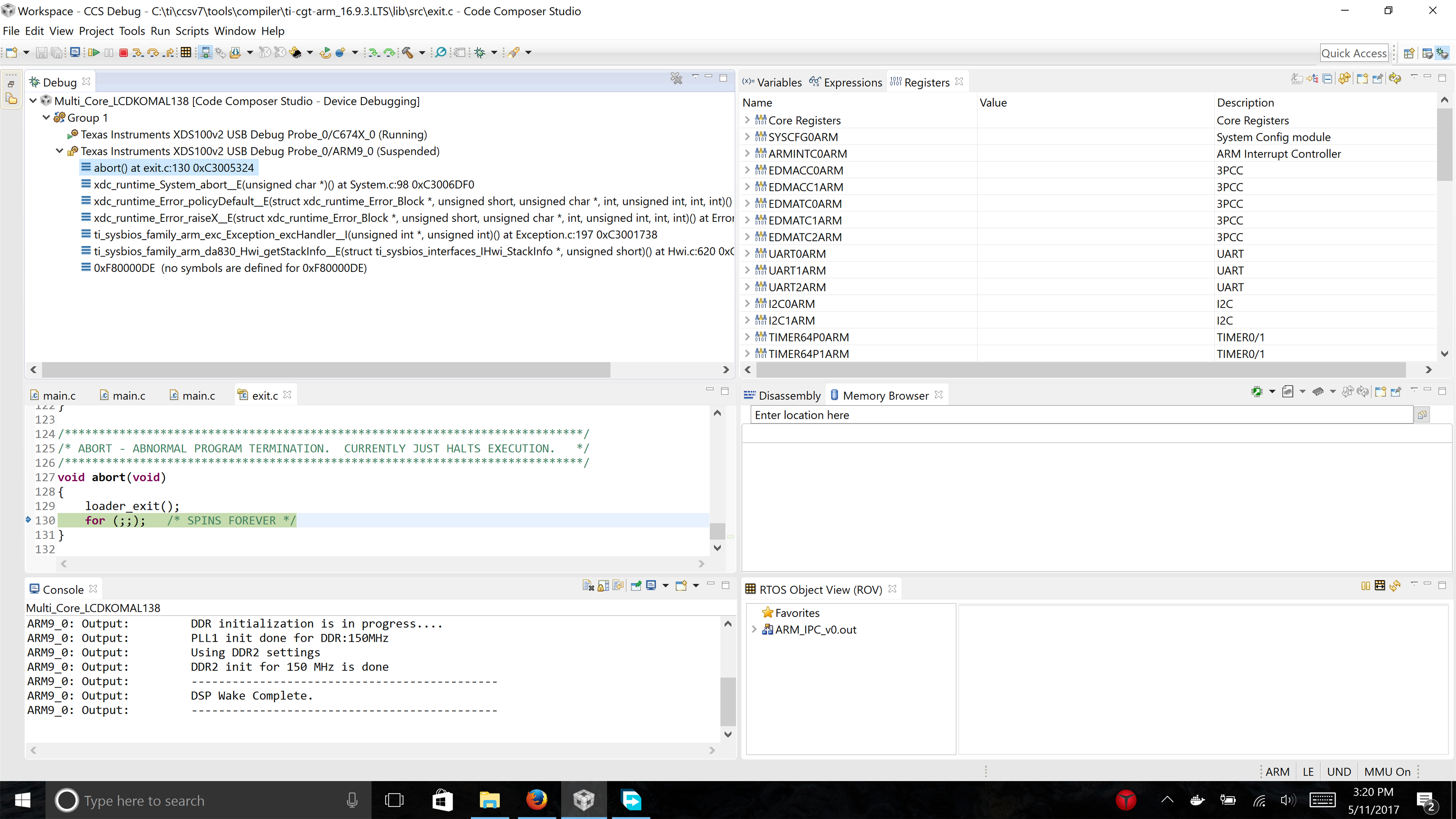
    But nothing happens as expected. sometimes I get an abort error, sometimes just nothing happens, ...

    I was wondering if someone could help me understand what I am doing wrong

    Thanks

  • I also tried to create specific debug configuration where CCS takes care of loading the program for the intended cores, but again the ARM core aborts.

    here is a screen shot

    I would appreciate if somebody could help me

    Thanks

  • it is very strange!!

    I loaded the program written for ARM core and it successfully ran and wrote 1 to the syscfg0 -> chipsig at every timer interrupt.
    Then I loaded the program written DSP core, and manually wrote 1 to syscfg0 -> chipsig, and DSP received interrupt and blinked the LED.
    But when I load both cores the ARM core aborts!!

    I would appreciate if somebody could help me.
  • There are many options to develop IPC code on this device. Could provide more details of what OS are you running on the ARM and DSP. the IPC in starterware is for bare-metal or no-OS development use case and provides very basic services for ARM to interrupt the DSP and pass a messages/buffers. The details of the implementation are provided here:
    processors.wiki.ti.com/.../StarterWare_01.10.01.01_User_Guide

    If you are using TI RTOS and/or Linux , in MCSDK 1.1 we provide a component called syslink that provide the ARM HLOS services and a IPC component for the TI RTOS that will run on the DSP to communicate with the syslink on ARM.

    processors.wiki.ti.com/.../MCSDK_OMAPL138_User_Guide_Chapter_Exploring
    processors.wiki.ti.com/.../Creating_CCS_Project_for_SysLink_samples

    We plan to provide a software refresh for this device at the end of this month where the TI SDK is taking a community approved approach to IPC using RemoteProc/RPMsg and IPC and this will be rolled out at the end of this month with some examples. Since this is new development, I would recommend looking into the actively maintained software rather than syslink which was released 3-4 years back.

    Regards,
    Rahul