This thread has been locked.

If you have a related question, please click the "Ask a related question" button in the top right corner. The newly created question will be automatically linked to this question.

SN54LS673: Timing diagram

Part Number: SN54LS673
Other Parts Discussed in Thread: SN74LV595A, SN74HC595B

Hi,

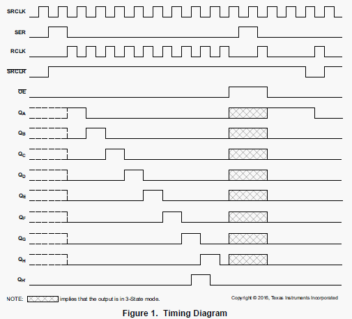
Do we have a timing diagram of SN54LS673 as we have for SN74LV595A as below?  Customer needs a similar part as SN74LV595A, but the shift needs to be 16-bit.  Is SN54LS673 a correct fit?  THanks!

Antony

  • Anthony,
    I am currently out of the office and will not be able to research this for a few days.
    Regards,
    Wade
  • Hey Anthony,

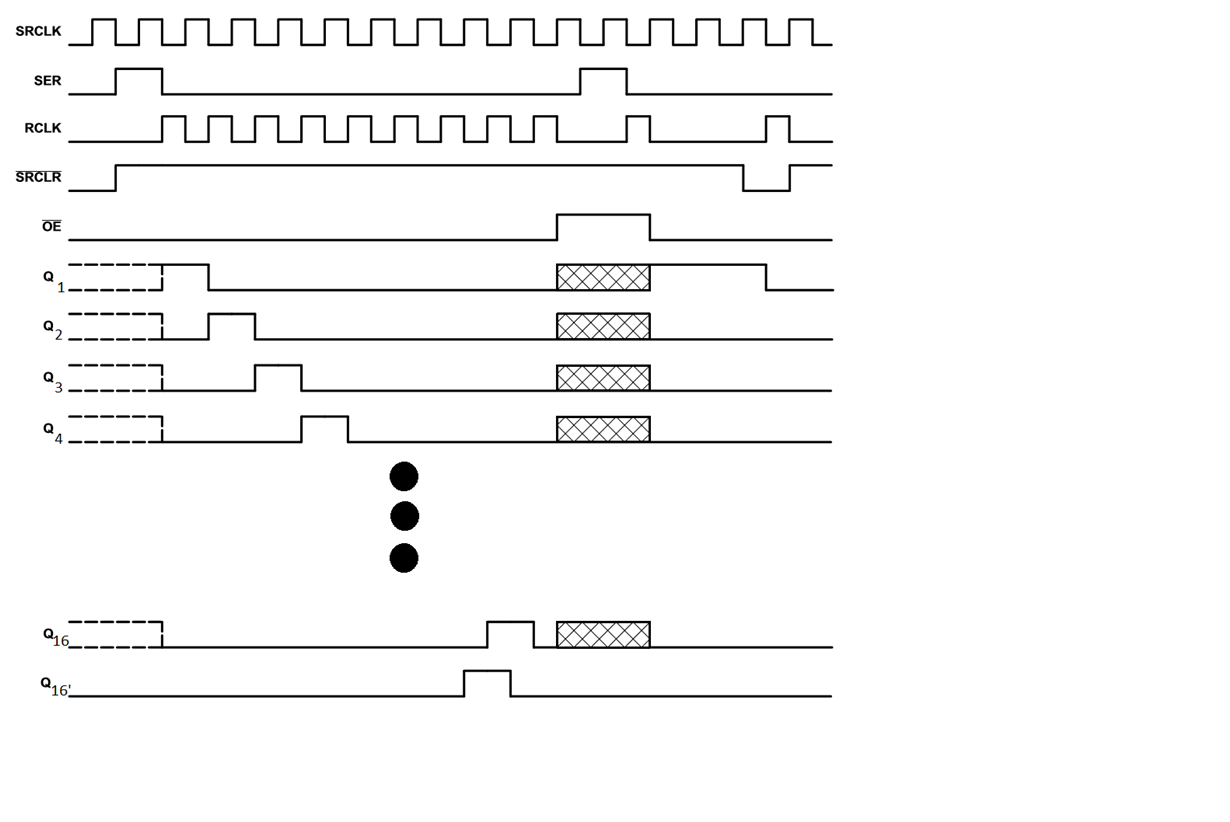
    We don't have an official timing diagram, but I was able to create what a 16 bit shift register would look like below. Will this work for your customer?

  • Hey Anthony,

    It has been mentioned to me that there would be more clock pulses in-between  the high of Q4 and the high pulse of Q16 because the high pulse has to travel to more outputs of the device. I should also make it more clear that this is not specifically SN54LS673, but a general 16-bit shift register. If you need an exact timing diagram I can make one for you.

    Thanks,

    Daniel 

  • HI Daniel,

    THanks.  Please create an exact timing diagram for customer to prevent confusion.  Additionally, customer is asking if we have any reference design schematics or ORCAD library for this part.  DO we have it?

    THanks!

    Antony

  • Hey Anthony,

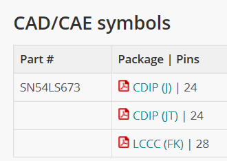
    As far as a reference design schematic we don't have one available, however depending on what package the customer wants we have the CAD/CAE symbols at the bottom of this page:

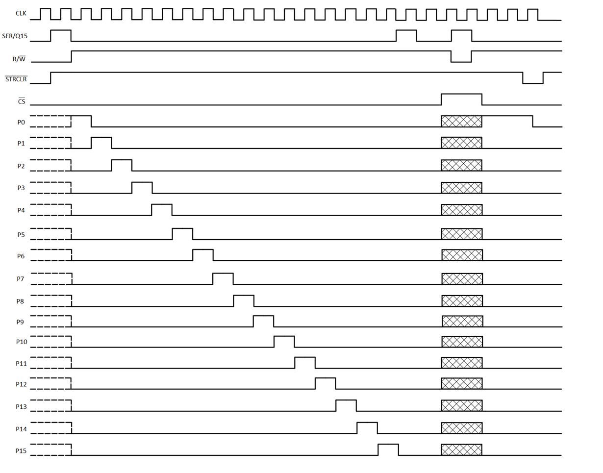
    Below is an exact timing diagram for the part, note that SER/Q15 may be different that what the customer is used to as the final output of the shift register and the serial input are the same pin and the function of the pin is changed using the R/nW pin.

    Thanks,

    Daniel

  • Hi Daniel,

    Regarding  CAD/CAE symbols you mentioned in http://www.ti.com/product/SN54LS673/pinout-quality#cadsymfoot  , we only list packages as below without the one (SOIC) that customer needs.

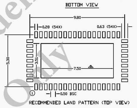
    Can you provide something like land pattern as below for this chip?  Customer's rule still need chip vendor to provide this information for their internal process. 

    THanks!

    Antony

  • Please indicate the orderable part number you are trying to find land pattern for.
    As far as I can tell, we only have the 3 versions and land patterns are available for each.
    Regards,
    Wade
  • Hi,

    Due to the cost concern, do you think customer can use two SN74HC595B chips to replace one SN74LS674DW?  How will you propose to do in schematics design?

    Thanks!

    Antony

  • Hi,

    What customer really needs is a 12-bit delay.  Do you think we can make it by using  two SN74HC595B as mentioned above?  Will there be any synchronization concern?

    Thanks!

    Antony

  • Anthony,
    I believe this can be done. The output of the first can be cascaded back to the SER pin of the second.
    It may make more sense to check with the commercial team as well, as you are now moving back to their product.
    I will ask them to comment on this post.
    Regards,
    Wade
  • Hi Antony,

    The SN74HC595B is ideal for what you are wanting to do if size and cost are a primary concern. We have a reference design that shows how to cascade the devices available here.

    I would recommend tying the SRCLK and RCLK lines together, then attaching your output to the 11th output position -- this will setup a 12 cycle delay (it takes N+1 clock pulses to reach the N output when SRCLK and RCLK are tied together)

    Please let me know if I can be of further assistance.

  • Hi Emrys,

    I guess your proposal is based on the description from datasheet as below, right?

    “Both the shift register clock (SRCLK) and storage register clock (RCLK) are positive-edge triggered. If both clocks are connected together, the shift register is always one clock pulse ahead of the storage register.”

    My question here is, what is the definition of “one clock pulse” here? Does it mean a full clock cycle or half clock cycle?

    From your reply, you mentioned “it takes N+1 clock pulses to reach the N output when SRCLK and RCLK are tied together".  If we check the “Figure 1. Timing Diagram” in the datasheet with half clock cycle delay between RCLK and SRCLK (with opposite phase), the delay from SER to QA is actually one clock cycle.  If SRCLK and RCLK are tied together, does it mean the delay from SER to QA would become 1+1 = 2 clock cycles? Why??

    In the last, please clarify if I understand your proposal correctly as below?

    • Tying RCLK/SRCLK of both chips all together.

    • Connrect QH of 1st chip to SER of 2nd chip.

    • Get the output (with 12 clock cycles of delay from SER of 1st chip) from QC of 2nd chip.

      Thanks!

    Antony

  • First, to disambiguate my terminology.  A clock pulse refers to a pulse that triggers the clock.  In logic systems, a pulse looks like this:

    (image borrowed from: https://en.wikipedia.org/wiki/Pulse_(signal_processing) )

    And for the SN74HC595B, the clock is triggered by a rising edge, thus it is triggered by the low to high transition in the shown waveform.

    When RCLK and SRCLK are tied together, they will trigger simultaneously, which means that whatever data was in the registers will be sent to the outputs (by RCLK) and, at the same time, the data in the registers will be shifted by one place.  Here's an example to try to clarify:

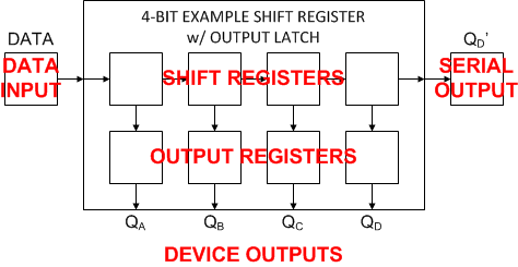
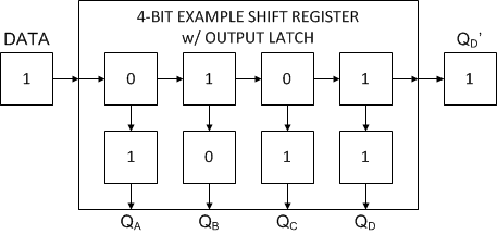
    For the purposes of explanation, I made a simple block diagram of a shift register with output registers, like HC595)

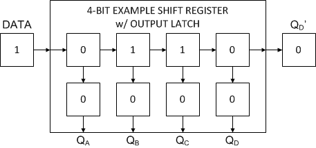
    Loading in some random data to start (0 1 1 0) we get this:

    Note that the data at the input won't be shifted in until a clock pulse happens on SRCLK, but the output at Q_D' is always the same as the data in register 'D' (the fourth register from the start). Also, the output registers are all starting at 0 in this example to show that RCLK causes the shift register data to get loaded into the output registers.

    After the first simultaneous pulse on SRCLK and RCLK with everything as shown above, you get this output:


    Note that the original bit pattern in the shift registers has now been loaded to the outputs (0 1 1 0), the data has been loaded into the shift register, and all shift register values have shifted by one to the right (1 0 1 1).

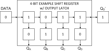
    Now apply another pulse at SRCLK and RCLK simultaneously:

    Now the serial shift registers contain 0101 and the outputs contain 1011.

    If you look at this purely from the outputs QA, QB, QC, QD, the outputs are behind the inputs by a clock cycle.

    i.e. If you want to load data into the shift register _and_ send it to the output registers, then you must clock the data in (4 bits = 4 clock pulses) and then send one additional clock pulse to get the data to the output (a total of 5 pulses, or N+1 with N being the number of bits loaded). For a system with 2 8-bit shift registers in series, you would need to load in 16 bits of data, then send a 17th bit to  get all 16 bits to the correct outputs.

    I hope this helps to clarify this a bit.