This thread has been locked.

If you have a related question, please click the "Ask a related question" button in the top right corner. The newly created question will be automatically linked to this question.

MSP430F6459-HIREL: Timers for Frequency signals

Part Number: MSP430F6459-HIREL
Other Parts Discussed in Thread: MSP430F6459

Greetings,

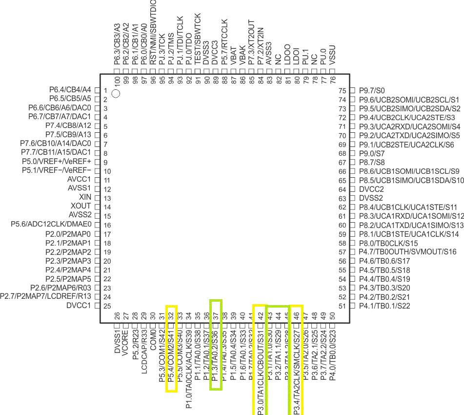
We're using MSP430F6459_HIREL microcontroller. Its new to us and we're running out of time. Our requirement is to provide 3 frequency signals ( Square wave ) as input to the microcontroller.  For now, we've given those signals to the pins: 34, 42 & 46. Are these pins suitable for this application? If not, please let us know the exact purpose of the respective pins. Also, suggest us the apt pins for frequency signals as input to the controller.

The frequency ranges are as follows:

1st : 15kHz,

2nd : 77Hz &

 3rd :  maximum Pulse rate : 2 pulse/sec

          minimum Pulse rate :  1 pulse /12 sec

all are Square wave only 

Thanks and regards,

Venkata Ramana

  • Hi,

    The apps engineer responsible for this device is currently out of the office. He will get back to you upon his return early next week.

    thanks,
    Christian
  • Please respond as soon as possible
  • Venkataramanu,
    Apologize for delay, I am back in the office.

    You indicate that these signals are inputs to the MCU. Can you indicate what you intend to do with the signals?
    Trigger ISR?
    If so, then you need to align on signals that are interrupt capable. This can be seen in the functional block diagram on page 2 and in terminal descriptions.
    P1.x, P2.x, P3.x, P4.x are all interrupt capable.
    The three signals you have chosen are all interrupt capable.

    If they do not need to be interrupt driven, then any available port can be used as a GPIO in input mode.

    Regards,
    Wade
  • Dear Wade,
    My intention is to monitor those signals. (like how we monitor the analog signals).
    Clearly we want to measure the Frequency (no of pulses or time period).
    for that one kindly suggest suitable pins

  • In user guide pins they've mentioned like these pins are used to give external reference clock for comparing(like internal clock reference).
    we don't require any external clock. Internal clock is OK for us so i changed these inputs to following
    37(P1.3/TA0.2)
    43(P3.1/TA1.0)
    44 (p3.2/TA1.1) capture pins.
    Correct me if I'm wrong. And Kindly suggest me suitable pins.
    regards
    Venkata Ramana

  • Venkata,
    I am uncertain what you mean by monitor. Do you need to count?, take some action at each event?

    The timers can be used for counting and triggering an interrupt after certain count of events.
    Or you can interrupt off the event itself and have the MCU take action.

    Fortunately, the pins you have selected can do both. They can operate as GPIO with interrupt. This will allow you to have the processor take action at each event.

    The pins TAx.CLK can also be used for each timer to count events. This will allow you to trigger an interrupt after a programmable number of events on that CLK.
    Regards,
    Wade
  • I just noticed you changed pins that you were referring to.
    The original pins 34,42,46, are the pins that can do both GPIO interrupt, or be used as CLK inputs to the timer to count events.
    Regards,
    Wade
  • What is the difference Between pins 34, 42, 46 and 37(P1.3/TA0.2), 43(P3.1/TA1.0), 44 (p3.2/TA1.1).

    What is the Significance 34, 42, 46. these signals are given as Timer clock input (1.General-purpose digital I/O with port interrupt. 2. Timer TA2 clock input. 3. SMCLK output. 4,.LCD segment output S27) here GPIO and LCD interface is ok. What are the Timer TA2 clock input. and SMCLK output

    General-purpose digital I/O with port interrupt
    Timer TA0 CCR2 capture: CCI2A input, compare: Out2 output
    LCD segment output S36

    I understood remaining timer pins are used as GPIO/Capture/ PWM output/ LCD interface

  • The first set of pins can be routed to TAX clock inputs. This allows you to count these events and trigger when a count has been achieved. The other pins do not have this capability. They both can be GPIOs with ability to trigger interrupt.

    Regards,
    Wade
  • Still I'm confused so I'm giving my Input signal details. 

    (RPM : square wave 0- 3.3Vp)

    If no signal = 0.0% rpm (RX buffer section)

    If 1020 Hz = 0.0% rpm

    elseIf 3400 Hz = 25.0% rpm

    elseIf 6800 Hz = 50.0% rpm

    elseIf 10200 Hz = 75.0% rpm

    else 13600 Hz = 100.0% rpm

    this is my input signal for this we need to calculate the frequency. Suggest suitable pins for this signal.

  • So, you are trying to take 3 signals, and measure the frequency of each signal?

    If so, I think your best approach would be to use the timers to count the clock transitions. After certain time period, you could grab the count values and calculate the frequency.

    I was searching the forums for solutions like this, and noted one that may be helpful to you.
    forum.43oh.com/.../

    There are other references in E2E posts on creating a frequency counter. You can search for "msp430 frequency counter" and get many hits.

    The example above uses 1 second as the timer interval to calculate frequency. The longer the time period, the more accurate the frequency measurement.

    It may also be possible to do this in capture mode, and calculate frequency based on timestamps. However this will suffer from poor resolution. It will depend on your needs. How accurate and how quickly does the measurement need to take place.

    Regards,
    Wade