This thread has been locked.

If you have a related question, please click the "Ask a related question" button in the top right corner. The newly created question will be automatically linked to this question.

ADC08D1520QML-SP: Dual Channel Mode: Configuration and Data Rate

Part Number: ADC08D1520QML-SP
Other Parts Discussed in Thread: ADC08D1520

Hello,

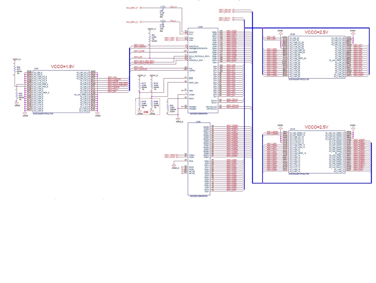
We are trying to use ADC08D1520 in dual channel mode and attached is the schematics for the ADC interface. We would like to sample the data at 250 Msps/channel. Right now, we are feeding in 250MHz clock as input clock to the ADC (CLK+/-). Is it right input frequency ? What would be output clock frequency from ADC (DCLK+/-, DCLK2+/-) ?

Following is our configuration sequence:

 x"001" & x"1" & x"92FF"; --Header & Reg Address & Reg Data(ConfigReg)
 x"001" & x"9" & x"27FF"; --Header & Reg Address & Reg Data(ExtConfigReg)
 x"001" & x"2" & x"007F"; --Header & Reg Address & Reg Data(IoffsetReg)
 x"001" & x"A" & x"007F"; --Header & Reg Address & Reg Data(QoffsetReg)
 x"001" & x"3" & x"F07F"; --Header & Reg Address & Reg Data(IfullscaleReg)
 x"001" & x"B" & x"F07F"; --Header & Reg Address & Reg Data(QfullscaleReg)
 x"001" & x"0" & x"FFFF"; --Header & Reg Address & Reg Data(CalibReg)

Can you please help us with the configuration sequence for the above mentioned datarate? 

Please let us know if you have any questions or concerns.

Thanks in advance

MK

  • Hello MK,

    That is correct.   If you want to run the part as a dual channel ADC, the clock speed and the sample rate are the same.  In your case for a 250 MSPS rate, the input clock should be set at 250 MHz.

    The output clock will depend upon how you configure the output.  In the most common 1:2 Demux, DDR output mode, the DCLK with be at 1/4 the input clock or 62.5 MHz in your case. 

    Kirby

  • Hi Kirby,

    Thank you for your prompt response. I am seeing 125MHz clock on DCLK+/- and none on DCLK2+/- (as if this is still acts as OR+/-). Does my configuration seems right to you ?

    Thanks

    MK

  • Hi Kirby,

    Just to add to the above message:

    Thank you for your prompt response. I am seeing 125MHz clock on DCLK+/- and none on DCLK2+/- (as if this is still acts as OR+/-). Does my configuration seems right to you ?

    I am using DCLK+/- (as clock), and  DI+/-,DId+/- (as Data) for Channel 1, and

                     DCLK2+/- (as clock), and  DQ+/-,DQd+/- (as Data) for Channel 2.

    As this is a time sensitive project, can we have a chat over the phone.

    I would appreciate if you could give me a call. You can reach me at (703) 628-1425.

    Thanks

    MK

  • Hi Kirby,

    Your call and support over the phone really helped. Thank you for the support.

    But, I have another question regarding DCLK_RST (configured as single ended). After power up I was able to do calibration (CAL) thru configuration registers. I do see CALRUN going high.

    But when I do soft reset (DLCK_RST) and try to calibrate then CALRUN doesn't go high.

    During soft reset... DCLK_RST is held high for 400 ns before I pull DLK_RST '0'.


    Thanks
    Madhu
  • Hi Madhu,

    After running any calibrations are you putting pin 30 back to logic-low?

    Both the cal pin (30) and the cal bit (address: 0h) have to be low before initiating a calibration cycle either with the cal pin or the SPI.

    Also besure that the cal bit is high for at least 1280 clock cycles before toggling it low again.