This thread has been locked.

If you have a related question, please click the "Ask a related question" button in the top right corner. The newly created question will be automatically linked to this question.

AFE5809EVM: SPI configuration for AFE5809

Part Number: AFE5809EVM
Other Parts Discussed in Thread: AFE5809,

Hello,

We're trying to configure SPI registers of AFE5809 using Zynq MicroZed, but unable to see any result. 

As mentioned in page 52, register maps in AFE5809 datasheet. We have followed the procedure exactly but still, see no result on the TSW1400GUI side

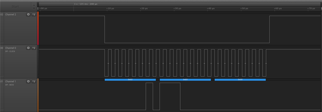
Here's the SPI waveforms seen on AFE5809 side, when configured through TSW1400GUI. And there is a ramp pattern see on the GUI die

24-bit SPI setting is to generate ramp test pattern. The data is verified through Logic Analyzer

#1

and, here is the SPI waveform, when configured through MicroZed, with the same register settings for ramp signal, but no result on TSW1400 GUI side

#2

For transfer, we are using standard 3.3V logic. The data matches, but there is no result. Is there something missing? Any help/suggestions would be really appreciated!

Further details:

Also, FB17 is removed, as suggested in this thread: https://e2e.ti.com/support/other_analog/imaging_afes/f/239/t/360353

The USB is disconnected and we are purely running the SPI from the on board pins.

SPI_DIG_EN is always high because demodulator registers are not being configured.

SCLK - 490 kHz

Data Width - 24 bits

Shift direction - MSB first

SCLK, SEN, SDATA, GND on P14 are exactly connected as it supposed to be.

Thanks!

  • Hello Vatsal,

    This device is covered by the Medical forum. I am moving it there, and they will be able to give you a proper response.

    Thanks,
  • Hi Vatsal,

    How are you initializing the device after removing FB17? Can you provide oscilloscope shots as opposed to logic analyzer captures?

    Also, can you please run your microcontroller logic at a slightly lower voltage--the max for the AFE5809 is 3.3V as shown below;

    SIncerely,

    Olu

  • Hello,

    I am running my Microcontroller logic with 3.3V not over than that but I tried to run at 2.5V before but didn't worked.

    I am not sure what you mean by Can you provide oscilloscope shots as opposed to logic analyzer captures?

    Thanks.
  • Hi Vatsal,

    I am asking for actual analog signal captures from an oscilloscope.
    Also, can you please walk me through your current procedure for configuring through MicroZed after powering up the AFE5809EVM--are you initializing the EVM using the AFE5809EVM's GUI or the MicroZed board?

    Sincerely,
    Olu
  • Hello,

    I want to eliminate AFE5809EVM's GUI. So I want to configure AFE5809EVM with Microzed. Anyhow, I removed FB17 so USB isolators are not powered up. So USB cable is isolated.

    I am connecting my SPI signal on the P14 jumper. Once I connect everything I run some register's settings. To test I am using inbuilt test pattern generator(Ramp signal) on AFE5809. Which can be accessed through 0x2 Register address.
    I am using disabling demodulator so I don's have to program profile RAM or profile coefficient.

    Regards,
    Vatsal
  • Hi Vatsal,

    The AFE5809EVM has an initialization routine at powerup/reset that includes setting the following registers to these values;

    Register 22 = 0x01

    Register 4 = 0x18.

    Subsequently, you can successfully observe the ramp signal after configuring register 2.

    Sincerely,

    Olu

  • For confirmation, we want to run test signals such as ramp without the AFE5809EVM's GUI.

    Is this the correct order of SPI transfer from the MicroZed - such that we see ramp signal on the LVDS output of AFE5809EVM?
    1. Normal operation - At 0x00 address, transfer 16 bit data: 0x00 0x00
    2. Disable demodulator: At 0x16 address, transfer 16 bit data: 0x00 0x01
    3. Ramp signal: At 0x02 address, transfer 16 bit data: 0xE0 0x00

    On every transaction, SEN signal is low for all 24 bit SPI operation. SPI_DIG_EN. CDCM_LE is high. PDN_GLOBAL, PDN_VCA and PDN_ADC is low.

    Please confirm if this is correct order of operation. Or could you tell us how you would do it?

    Thanks.
  • Hi Vatsal,

    At startup (or after a software reset);

    • At address 0x16, transfer 16 bit data: 0x00 0x01
    • At address 0x04, transfer 16 bit data: 0x00 0x18
    • For ramp signal, at address 0x02, transfer 16 bit data: 0xE0 0x00.

    For each SPI transaction, drive SEN low at the beginning of the transmission then high at the end.

    Sincerely,

    Olu

  • Yes, we understand sequence for SPI transfer. I'm driving SEN low at the beginning of the transmission then high at the end already. But there is  still no see ramp signal.

    Have you tried this procedure and could you confirm that it is working for you and you are able to program SPI with no USB cable of AFE5809EVM connected and also FB7 disconnected?

    Thanks.

  • *FB17* disconnected
  • Hi Vatsal,

    I have successfully used the MSP432 running SPI with no USB/GUI to bring up the AFE5809EVM at startup or after a software reset.

    I suggest that you confirm whether you can communicate with the AFE5809 via SPI first before trying to do a reset.

    Try soldering wires to the pads for FB17 that you can connect/disconnect at will. Then connect the wires thereby powering up the isolators before bringing up the board with the GUI (make sure the MicroZed is powered down if connected to P14). Confirm you can change from a ramp signal to analog and back using the GUI and if you monitor the SPI lines on P14, you should see the commands sent by the GUI.

    Then without powering down/resetting the AFE5809EVM, disconnect the wires powering up the isolators so that only your MicroZed SPI lines are connected to the AFE5809's SPI pins. Since the GUI has already initialized the AFE5809EVM for you, you can now try different SPI commands using your MicroZed board. You can do a register readback (monitor SDOUT on TP12) to verify that your board can communicate with the AFE5809EVM--register 4 should hold 0x18 for example.

    Also note that 0x0002 has to be written to register 0 (setting the resgister_readout_enable bit) in order to put the device in read mode as opposed to write mode.

    Sincerely,

    Olu

  • Hi Olu,

    I tried why you said but It didn't work. I am using this setup, 

    Can you please let me know your AFE current consumption when you disconnect FB17? 

    When USB connected : 600mA

    When FB removed : 1.02A

    Is it the case with your setup? 

    Thanks.

  • Hi Vastal,

    You shouldn't be drawing that much current with FB17 removed.
    When the AFE5809EVM is powered up with FB17 connected but the GUI closed, current draw is 0.721A.
    Running the GUI with FB17 attached drops the current draw to 0.591A.

    On the other hand, if FB17 is removed after initializing the EVM using the GUI, the current drops to 0.563A.
    Lastly, if the board is powered up with FB17 removed, draw is 0.688A.

    Sincerely,
    Olu
  • Hi Olu,

    Thanks for letting me know the current draw of AFE5809EVM.
    My Currernt Draw is
    1. When the AFE5809EVM is powered up with FB17 connected but the GUI closed : 0.60A
    2. Running the GUI with FB17 attached : 0.78A
    3. FB17 is removed after initializing the EVM using the GUI : 0.76A
    4. If the board is powered up with FB17 removed : 1.03A

    Can you please tell me what can be the problem? Please, Let me know If I have to run some more test.

    Thank you.
  • Hello Olu,

    Can you please confirm that you able to configure AFE5809EVM with FB17 disconnected, Are you configuring profile RAM also if you don't use Demodulator?
  • Hi Vatsal,

    I am not quite sure why you having trouble configuring the SPI on your end.

    The last thing I can think of is making sure that the phase and polarity of the MicroZed's SPI interface match the AFE5809's timing diagram. Have you used the SPI interface on the MicroZed to communicate with another device before?

    Sincerely,

    Olu

  • Hello Olu,

    Well, It is working now, I am able to configure AFE chip without GUI(FB17) disconnected.

    Current draw on start-up is still 1.02A but when I trasfer Register Values it comes down to 0.83A. It is different then the current draw you have but I can see the SPI working now.

    Thanks for the help! Really appreciate it!

    Regards,
    Vatsal
  • Dear Vatsal,
    What I meant is that, would you mind sharing your solution with me too? Or at least may I have your C code? I'm using an OMAP L138 LCDK and I cannot configure the AFE5809 EVM.
    If we could communicate over the phone or the internet, it would really appreciate the help. I'm a student in Korea and I've been stuck with this step of my project for a long time.
    Thank you :)
  • Dear Olu,
    Could you please share your C code? As you know, I'm also in desperate need to initiate my AFE5809 EVM using OMAP L138 LCDK.
    I could modify your code for OMAP L138 LCDK.
    Your help means a lot to me. Thank you :)
  • Hi Sajad,

    This thread is closed. Please open up another thread in the future if you have a specific question. Unfortunately, I cannot share my code as it MSP43x-specific register level code, not standalone plus it was not written with public distribution in mind.

    Although I am not familiar with the OMAP L138 platform, I did look at some of the board schematics and it looks like it uses a C6748 processor and you have two SPI interfaces you can work with. The C67x forums are here and I am sure they have code examples and expertise to help you get started on communicating with the AFE5809EVM via SPI.

    Sincerely,

    Olu

  • Hello Sajad,

    Sorry, but I can not share my code as it for Zynq7020 FPGA and It depends on the hardware design I created on the FPGA. But I think there are lots of information available on this thread and some other threads to understand SPI programming for AFE5809 chip.

    I would suggest, please confirm that the waveform you are generating is exactly same i.e CPOL and CPHA.

    Good luck!

    Regards,
    Vatsal Naik
  • Dear Vatsal Naik,

    Thank you for your reply.

    The good news is that I have solved the issue with the SPI connection, thanks to your information in this thread. I have another issue that I hope you can help me solve.

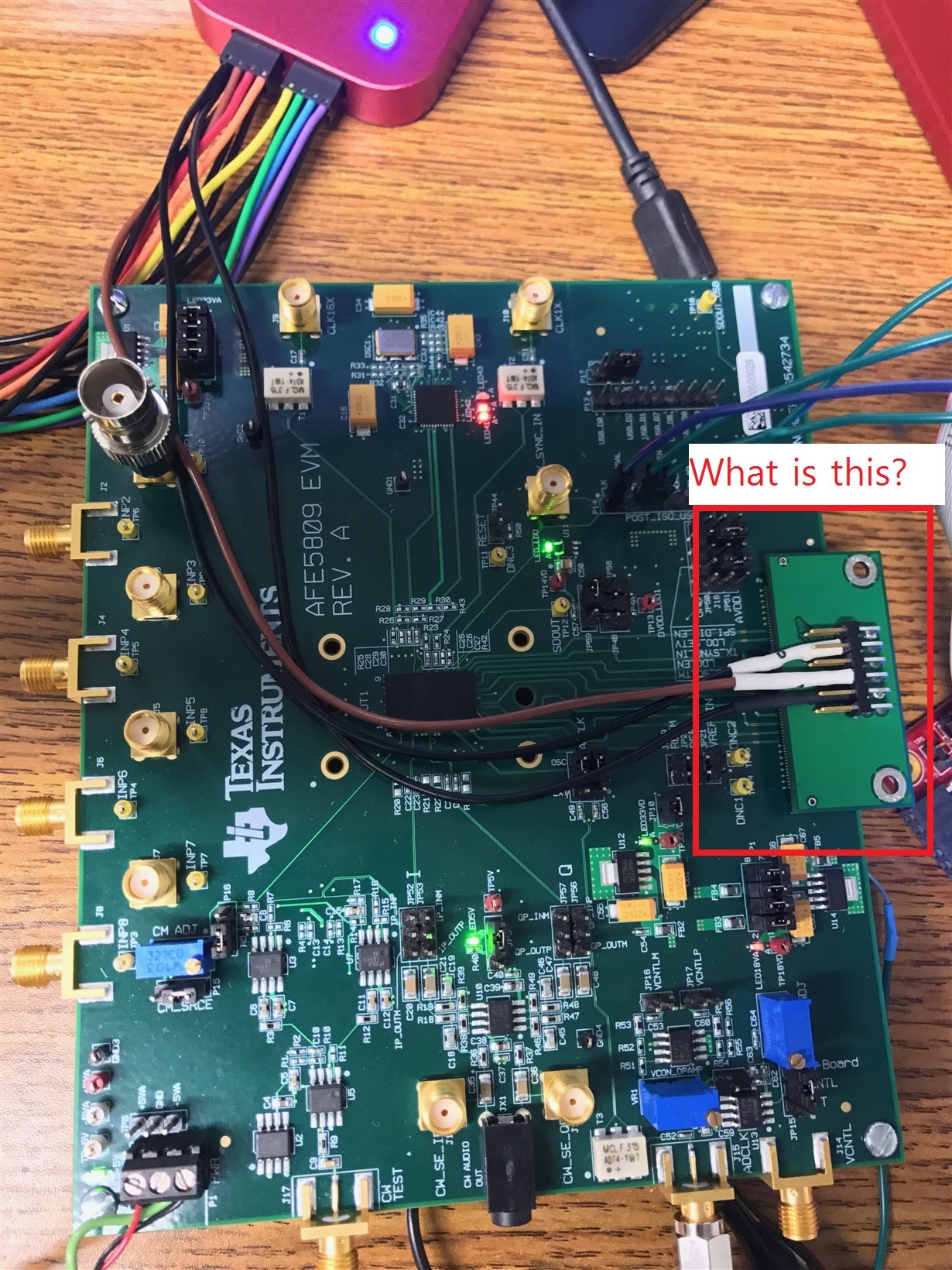
    The following image is from your previous post. What is that connector that you are using to read the output of LVDS?

  • Hi Sajad,
    I am using that connector to observe LVDS signal.