This thread has been locked.

If you have a related question, please click the "Ask a related question" button in the top right corner. The newly created question will be automatically linked to this question.

AFE4300EVM-PDK: Impedance Measurement and transferring data using SPI

Other Parts Discussed in Thread: AFE4300EVM-PDK, AFE4300

We're trying to use the AFE4300EVM-PDK to measure body fat percentage. We want to use a Raspberry Pi to control the AFE using SPI, and have the AFE send body fat measurements via SPI back to the Pi. We've looked at the user guide (sbas586b) and the application note (sbaa202) extensively, and couldn't find how to interface the board with an external device such as the Raspberry Pi.

  • Is it possible to set up the AFE4300EVM-PDK to perform the impedance measurements without using the GUI, and solely by interfacing the board for SPI communication with the Raspberry Pi?
  • We were also wondering if the ADC_DATA_RESULT register contained the final result of the impedance measurement that we should send to the Pi using SPI? If not, is there a technical reference manual that provides a full documentation of the registers we may need to use?

In the application note, we went through the steps for setting up and performing FWR bio-impedance measurements.

  • Is it possible to calibrate the AFE for impedance measurement using resistors that are not the reference resistors (R56-59)?
  • In the WriteRegisters.csv file, how does the default value of 4130 correspond to an ADC Data rate of 64sps? And how can we change this frequency value to get a different data rate?

Thank you!

  • Hi Nimish,

    To interface Raspberry Pi (Rpi) with the AFE4300EVM, you have to
    1) Remove all the connections of digital signals between MSP430 and AFE4300.
    2) Blue wire all the digital signal from AFE4300 to Rpi.
    3) Power the AFE4300 using the on board regulators.

    Yes, you can connect AFE4300 to Rpi and program the Rpi to handle all the task solely such as programming the AFE4300, calibration, deducing the body impedance using information from calibration.

    ADC_DATA_RESULT contains the output of the ADC. To find the impedance you have to find excitation current and the offset from the calibration routine ( which is done with two known resistors).

    You can calibrate the AFE with the external known resistors other than R56-R59 by using other unused IOUTs and VSENSEs channels.

    Data rate is set using D6, D5 and D4 of ADC_CONTROL_REGISTER1. "4130" is the hex value for this register (i.e. 0x4130). So 0x4130 will have D6:D4 as 011, which is setting for 64sps. If you wan to change the data rate you have to set D6:D4 of ADC_CONTROL_REGISTER1 with the appropriate values.

    Regards,
    Prabin
  • Hi Prabin,

    Thank you for your help. I have an additional follow up question.

    To power the AFE we need to use j102, correct? However, the pinout for j102 is not listed anywhere. What is each pin of j102?
  • Hi Nimish,

    For the pinout if J102 , you can look at J2 of MMB3 board.
    Schematic of MMB3 board can be found at
    ftp.ti.com/.../MMB3_Schematic.pdf

    Alternatively, you can power the AFE4300 EVM without the MMB3 board using J2 of AFE4300 EVM.

    Regards
    Prabin
  • Hi Prabin,

    Thank for all the help so far. We are currently having a problem with calibrating the board using the GUI. We have tried to calibrate the board using the multiple different sets of the on board resistors.The issue is that the mag for R1 and R2 that we obtain from the calibration seems too low. Do you know what might be causing this?
  • Hi Nimish,

    Can you please share the circuit used for the calibration stating "R1" and "R2"?

    Regards,
    Prabin
  • Hi Prabin,

    Would it be possible to talk with you over the phone or a webchat? We have a lot of questions regarding connecting the AFE4300EVM to the Raspberry Pi (such as clocking the board, powering the board, performing impedance measurement over SPI), and feel that a phone call would be much more efficient for both of us than asking you questions over this forum. You can call us at 512-862-7345

    Thanks!
  • Hi Nimish,

    I totally understand your situation but I feel discussing over the forum not only solves your problem, it also helps other members facing similar issues. This approach truly reflects the main objective of having this forum.
    So I suggest lets try resolving all the issues one at a time and see how it goes. That being said if necessary we can definitely have a call.

    Regards,
    Prabin
  • Hi Prabin,

    We are connecting the AFE4300EVM to the Pi using SPI, and have some more questions:

    • Do we need to check RDY before reading ADC_DATA_RESULT everytime to make sure data is ready?
    • Do we always leave STE on J103 at 0?
    • What is SDQ on J103? And how do we modify it to control SPI?
    • Is ADC_PD the same thing as ADC_PDN on page 21 of the AFE4300 data sheet (sbas586)?
    • To take a single shot measurement, we write 1 to ADC_CONV_MODE, and ADC_PD, then we read ADC_CONV_MODE until that bit it is a 1. At this point ADC_PD should be 0, then we read ADC_DATA_RESULT. Is this what we need to do? If not, can you clarify the process for taking a single shot measurement?
    • In FWR mode, once we have read ADC_DATA_RESULT, do we plug it into the linear function we obtained during calibration to get the impedance measurement? In other words, plug in for v in the equation Mag = m*v-o from the applications note "Impedance Measurement with the AFE4300" (SBAA202)?

    Thanks!

  • Hi Nimish,

    Here are the answers,

    #1 : Yes, you need to check ADC_RDY before you read data.

    #2: If you don't have any other slave in the SPI bus, then you can tie STE to 0.

    #3: SDQ in J103 is not needed. Leave it floating.

    #4: For single-shot conversion, follow the given steps below:

    • Set ADC_PD = 1
    • Set ADC_CONV_MODE = 1
    • Wait for ADC_RDY
    • Read the Data.
    • Reset ADC_CONV_MODE, i.e. ADC_CONV_MODE = 0
    • For next capture, follow from 2nd step.

    #5: Yes, you have to put ADC_DATA_RESULT as 'v' in the equation Mag = m*v + o, Where 'm' and 'o' are the slope and offset obtained form the calibration routine.

    Regards,

    Prabin

  • To confirm, is ADC_RDY the same thing as the RDY pin on the J103 (pin 15)? Also, is this an active_low pin (ie RDY==LOW indicates data is available)?

    Additionally, it looks like the SPI clock is 2MHz (a period of 500ns) when we measure it with an oscilloscope while connected to the MMB3. However, the documentation says that SCLk period 250ns, which would be 4MHz. Is the documentation wrong or what frequency should we be providing to the clock?

    What we need to do with the Raspberry Pi can be summarized as follows. Can you confirm this is correct or tell us how we are wrong:

    Initialize:

    • write 0x0000 to MISC_REGISTER1
    • write 0xFFFF to MISC_REGISTER2
    • write 0x6006 to DEVICE_CONTROL1 //this sets the device for body composition, which is what we're doing
    • write 0x0032 to DAC_FREQ //this should initialzie the DAC_CLOCK to 50kHZ, which is what the GUI uses
    • write 0x0063 to ADC_CONTROL_REGISTER2
    • write 0x0030 to MISC_REGISTER3

    Calibrate:

    • //use 750 ohm resistor
    • write 0x0201 to VSENSE_MUX
    • write 0x0201 to ISW_MUX
    • result 1 = Measure //see below
    • //use 950 ohm resistor
    • write 0x0202 to VSENSE_MUX
    • write 0x0202 to ISW_MUX
    • result 2 = measure //see below
    • //determine slope and offset using two results

    Measure:

    • write 0xC1C0 to ADC_CONTROL_REGISTER1 //this sets ADC_PD to 1, ADC_CONV_MODE to 1, ADC_DATA_RATE to 128 SPS (default), and ADC_MEAS_MODE to differential
    • while(RDY==HIGH) { //wait or sleep, data is not ready }
    • write 0x2000 to SPI MOSI //read request for ADC_DATA_REGISTER
    • result = read from SPI MISO
    • write 0x41C
    • 0 to ADC_CONTROL_REGISTER1 //sets ADC_CONV_MODE = 0
    • return result

    Thanks for all of the help!

  • Hi Prabin,

    We've attached our code, which implements the pseudocode in the last post.

    We're using WiringPi's SPI library to do SPI. However, the RDY pin is never going back to LOW and attempting to read the ADC_DATA_RESULT gives 0. Do you know why the RDY pin is never being set to high? The documentation suggests we should perhaps be checking ADC_PD or ADC_CONV_MODE on the ADC_CONTROL_REGISTER1, but we are not sure. Also, do you know if we need more manual control of SPI or is just using the library fine?

    BIA.hBIA.cpp

  • Hi Nimish,

    Yes, ADC_RDY is RDY pin of the AFE4300 and it is active low signal.
    AFE4300 supports SPI upto 4MHz ( 250nS) but any time you can lower the speed. That is why in our EVM the SPI is configured to 2MHz.

    Comments for your code.
    1) Are you using on board reference resistors ( R56 and R57) for calibration? if yes, can you please remove R58 and R59. Change R57 to 950 Ohm.
    2) For reading ADC_DATA_REGISTER you have transfer 3 bytes ( 0x200000) and simultaneously sample SOMI . Last 2 bytes (out of 3) will contain the ADC_DATA_REGISTER.

    Is there any specific reason for choosing single-shot mode?
    I would suggest its good to get everything up and running in continuous mode ( at least for debug purpose as it will confirm the setup).
    Later you can switch to single-shot mode.

    Regards,
    Prabin

  • Hi Prabin,

    We updated our code to do continuous mode, (we first call the constructor and then testContinuous). However, the RDY pin is always high and the value of the ADC_DATA_RESULT is always 0. I'm testing by measuring across R56, so we should be getting a nonzero code back. Why are we not getting a reasonable number for the code?

    We were using the on board reference resistors (R56 and R57) to calibrate. What do you mean by removing R58 and R59? Also, isn't R57 already a 950 ohm resistor? That's a part of the board so we can't change that.

    Thanks

    6330.BIA.h0044.BIA.cpp

  • Hi Nimish,

    Are you giving 1MHz signal to CLK pin?

    Also, can you verify whether SPI write is happening ?  Follow the given steps below to verify SPI write.

    1) Do the hardware reset.

    2) Measure voltage at VLDO pin . Should be ~0V

    3) Enable weight scale (i.e. write 0x6005 to DEVICE_CONTROL1)

    4) Measure voltage at VLDO pin . Should be ~1.7V

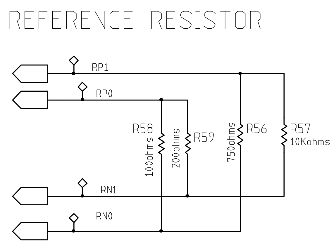
    Given below is the schematic for reference resistor 

    As seen in the image, R56, R57, R58, and R59 are connected in series. So if you are measuring R57, you will get value for R57 || (R56 + R58 + R59). This is why I suggested you to remove R58 and R59.

    From the image, the value for R57 is 10Kohm ( not 950 Ohm).

    Regards,

    Prabin

  • Hey Prabin,

    We realized that our code was not properly clocking the AFE4300. We aren't sure why, but we found another python library (pigpio) and reimplemented our code. Now we do receive codes when we try to calibrate. We receive ~1500-2000 when calibrating with R56 and ~3000-3500 when calibrating with R57. We compared these codes to the GUI using a low level configuration of the registers as well as using the tool for continuous capture of the ADC. In both of these, we got ~9000-9500 for R56 (setting VSENSE/ISW to 0x0201) and ~12000-12500 for R57(setting VSENSE/ISW to 0x0201). We've uploaded our python code as well (the forum didn't let us upload a .py file, so it's attached as a .txt). Do you know why these codes are so far off what is expected?

    Also, what registers/values do we need to write (and in what order) to obtain a single shot impedance using a tetrapolar configuration?

    We are not going to take out R58 and R59 because if you do the computation with the resistors in parallel, R56||(R57+R58+R59) = 700 and R57||(R56+R58+r59) = 950, which is where the documentation (and we) got the values from.

    Thanks!

    Nimish

    BIA.txt
    import pigpio
    import time
    
    
    CLK_PIN = 4
    CLK_FREQ = 1000000
    RDY_PIN = 16
    
    SPI_FREQ = 1000000
    mode = 1
    spi_handle = None
    
    REG_DEVICE_CONTROL_1 = 0x09
    REG_DEVICE_CONTROL_2 = 0x0F
    REG_ADC_DATA_RESULT  = 0x00
    REG_ADC_CONTROL_1    = 0x01
    REG_ADC_CONTROL_2    = 0x10
    REG_ISW_MUX          = 0x0A
    REG_VSENSE_MUX       = 0x0B
    REG_DAC_FREQ         = 0x0E
    REG_MISC_1           = 0x02
    REG_MISC_2           = 0x03
    REG_MISC_3           = 0x1A
    REG_WEIGHT_SCALE     = 0x0D
    REG_IQ_MODE_ENABLE   = 0x0C
    
    
    pi = pigpio.pi()
    
    def turn_on_clock():
      pi.hardware_clock(CLK_PIN, CLK_FREQ)
    
    
    def turn_off_clock():
      pi.hardware_clock(CLK_PIN, 0)
    
    def spi_init():
      global spi_handle
      spi_handle = pi.spi_open(0, SPI_FREQ, mode)
    #  print(spi_handle)
    
    def read(register):
      packet = []
      packet.append(0x20 | (0x1f & register))
      packet.append(0x00)
      packet.append(0x00)
      (count, data) = pi.spi_xfer(spi_handle, packet)
    #print("read sent "+(','.join(format(p, "04X") for p in packet)))
      if count < 3:
        print("ERROR: read received "+str(count)+" bytes: "+(','.join(format(d, "#04X") for d in data)))
      print("read received "+str(count)+" bytes: "+(','.join(format(d, "#04X") for d in data)))
      return (0xff00 & (data[1]<<8)) | (0xff & packet[2])
    
    
    def write(register, data):
      packet = []
      packet.append(0x1f & register);
      packet.append(0xff & (data >> 8));
      packet.append(0xff & data);
    #print(','.join(format(p, "#04X") for p in packet))
    #print(spi_handle)
      (count, data) = pi.spi_xfer(spi_handle, packet)
      print("write sent "+(','.join(format(p, "04X") for p in packet)))
      if count < 3:
        print("ERROR: write received "+str(count)+" bytes: "+(','.join(format(d, "#04X") for d in data)))
    # print("write received "+str(count)+" bytes: "+(','.join(format(d, "#04X") for d in data)))
    
    def measure():
      write(REG_ADC_CONTROL_1, 0xC1C0)
      while pi.read(RDY_PIN) > 0:
        time.sleep(0.001)
        print("shlep")
      data = read(REG_ADC_DATA_RESULT)
      write(REG_ADC_CONTROL_1, 0x41C0)
      return data
    
    def calibrate():
      write(REG_VSENSE_MUX, 0x0201)
      write(REG_ISW_MUX, 0x0201)
      code1 = measure()
    
      write(REG_VSENSE_MUX, 0x0202)
      write(REG_ISW_MUX, 0x0202)
      code2 = measure()
    
      print("Calibrate: code1: "+str(code1)+", code2: "+str(code2))
    
    def main():
      turn_on_clock()
      pi.set_mode(RDY_PIN, pigpio.INPUT)
      spi_init()
    
      #board init
      print("init registers:")
      write(REG_MISC_1, 0x0000)
      write(REG_MISC_2, 0xFFFF);
      write(REG_DEVICE_CONTROL_1, 0x6006);
      write(REG_DAC_FREQ, 0x0032);
      write(REG_ADC_CONTROL_2, 0x0063);
      write(REG_MISC_3, 0x0030);
      write(REG_WEIGHT_SCALE, 0x0000);
      write(REG_IQ_MODE_ENABLE, 0x0000);
      write(REG_DEVICE_CONTROL_2, 0x0000);
      print("done with init registers\n")
    
      calibrate()
      print(spi_handle)
    #time.sleep(5)
      pi.spi_close(spi_handle)
      turn_off_clock()
    
    
    main()
    

  • Hi Nimish,

    I went through your code, the return statement of "read" function should be

    return (0xff00 & (data[1]<<8)) | (0xff & data [2])

    The steps for single-shot mode has been already mentioned in earlier replies. Also your "Measure" function is doing single-shot conversion. For continuous conversion mode ADC_PD should be 0.

    For reference register, as long as you are accounting for series/parallel resistors in the calibration you are good to go.

    Regards,

    Prabin