This thread has been locked.

If you have a related question, please click the "Ask a related question" button in the top right corner. The newly created question will be automatically linked to this question.

Linux/ADS5263: Real noise floor of high speed data converters

Part Number: ADS5263

Tool/software: Linux

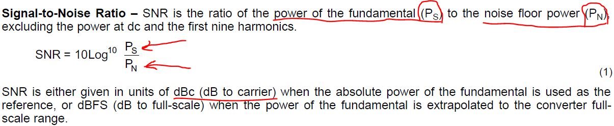
I working with ads5263. In dokumentation i see SNR = 84.1 dBFS for 15 MHz input signal with 100 MSPS clock signal. Teoretically, in BW (bandwidth) = 6 Hz i must have noise floor -137 dBFS.  FS = 16 dBm. I analyze the noise floor in the BW =  6 Hz in the absence of an input signal. In may case i have -125 dBF in BW = 6 Hz.

Theoretical calculation:  Noise Floor = FS - SNR - 10*Lg(fs:(2*BW)).
where:
FS - full scale signal (for ads5263 FS = 16 dBm);
SNR - signal to noise ratio (for ads5263 SNR = 84.1 dBFS);
BW - the band in which we work (6 Hz);
fs - sampling frequency.

So! The result of  theoretical calculation is -137 dBFS.
Real result (result obtained in practice) is -125 dBFS.

Why the result obtained in practice does not coincide with the theory?

Perhaps I misunderstand the documentation or my calculation is incorrect.

Help my please understand these problem.

  • Hi Val,

    How are you?

    Thank you for using our ADS5263 device.

    We will look into your questions and reply to you very soon.

    Thank you again.

    Best regards,

    Chen

  • Hi Chen, thank you for agreeing to help me, I'll be waiting for your reply.

    Best regards, Val.

  • Hi Val,

    How are you?

    Thanks for using our ADS5263 device.

    Please let's take a look from the user's guide shown as below.

    (Because we don't know how your setup for the clock hardware on your board looks.)

    Here shows one example which we are using on the ADS5263 EVM.

    Please follow its suggestion to set about 1.5Vpp sinewave at the differential clock pins.

    Hope this can help you get very closer to the ideal result.

    Thank you!

    Thank you!

    Have a nice day.

    Best regards,

    Chen

  • We did as you say. We used low jitter sinusoidal clock 1.5 Vp-p. But noise floor which we achieved was -122 dBm in BW (bandwidth) = 6 Hz. Theoretical calculation was -137 dBm.

  • I meant that the minimum signal level we could see was -122 dBm. The input frequency was 30 MHz, Sampling clock was 100 MSPS, low jitter sinusoidal signal 1.5 Vp-p.
  • Hi Chen, can you tell me minimum signal level (in dBm) which ads5263 can receive and in what conditions (fin, BW, FFT et cetera).
    Thank you,
    Best regards
    Val.
  • Hi Val,

    How are you?

    Thank you for letting us know more details about your ADS5263 clock settings. That looks great.

    In the 16-bit Mode of using ADS5263 device, it is 4Vpp Full-Scale (FS) Differential Input signal range

    and we can capture ADS5263 Output Raw Data from -32768 to 32767 range (in 2's complement mode format).

    So if our input differential signal is 4Vpp, then we will receive our Fundamental signal fin = 0dBFS.

    (in this case, its SNR in dBc => SNR in dBFS domain)

    Also if our input differential signal is 1Vpp, then we will receive our Fundamental signal fin = -12dBFS.

    (in this case, its SNR in dBc => SNR+12 in dBFS domain)

    Could you please let us know what Vpp your input differential sinewave signal is ?

    Thank you!

    Have a nice day!

    Best regards,

    Chen

  • Hi Chen,

    How are you?

    Thanks for your reply.

    Our differential input signal is 0.616 microvolt p-p (-120 dBm) at frequency 30 MHz and BW  = 6 Hz. 50 Ohm system.

    Best regards,

    Val.

  • Hi Val,

    How are you?

    We were doing very similar test conditions (as you mentioned) in our bench here

    to test ADS5263 EVM by using TSW1400 board to capture the output data from ADS5263 device.

    1) Here are the settings including input signal freq=30MHz, input clock freq=100MHz and more:


    2) Then we used TSW1400 board to capture the output data from ADS5263 device and

    also use its GUI to calculate the fundamental (in dBFS) and SNR (in dBc)

    3) Then we could calculate noise floor again (by using the equation you sent to us)

    shown as below. As you can see we can get very close noise floor test result to

    the theoretical calculation.

    Please take a look:

    4) Also please double check the following 2 Jumpers are connected correctly.

    Thank you very much!

    Have a nice day!

    Best regards,

    Chen

  • Hi Val,

    In addition to Chen's detailed response above, I am curious about the formula you posted for calculating the ADC's noise.

    Is that formula supposed to be for ADCs or amplifiers?

    SIncerely,

    Olu

  • Hi Olu.

    In the begining of this topick about ADS5263, i posted formula 

    Noise Floor = FS - SNR - 10*Lg(fs:(2*BW))

    where:
    FS - full scale signal (for ads5263 FS = 16 dBm);
    SNR - signal to noise ratio (for ads5263 SNR = 84.1 dBFS);
    BW - the band in which we work (6 Hz);
    fs - sampling frequency.

    This is formula for calculating noise floor of ADCs.

  • Thank you Chen for you reply!
    Best regards,
    Val
  • Hi Olu.

    In the begining of this topick about ADS5263, i posted formula

    Noise Floor = FS - SNR - 10*Lg(fs:(2*BW))

    where:
    FS - full scale signal (for ads5263 FS = 16 dBm);
    SNR - signal to noise ratio (for ads5263 SNR = 84.1 dBFS);
    BW - the band in which we work (6 Hz);
    fs - sampling frequency.

    This is formula for calculating noise floor of ADCs. I met this formula in the literature about the ADC

    Best regards,
    Val
  • Hi Val,

    Can you please send me a link to the literature? Thanks.

    Sincerely,
    Olu
  • Hi Olu.

    The book title is

    Data Converters
    by
    FRANCO MALOBERTI
    Pavia University, Italy.

    Best regards, 

    Val.

  • Hi Chen, could you please explain how can i finde out SNR (dBc) from GUI, i mean how i can obtain SNR (dBc) for ADC at all? I can't understand why SNR = -31.759 (dBc), because in the program window i see 15 dBc max.

    And one more thing, in formula of Noise floore calculation you get -141dBFS, why not -141 dBm, becaus FS in dBm.

    Best regards, 

    Val.

  • Hi Val,

    I think you are misunderstanding the noise floor formula. The first page of this app note talks about the difference between noise spectral density and total noise power integrated over the Nyquist bandwidth.

    The dB level of the "visual noise floor" you see above is dependent on the number of points used in HSDC pro's FFT but the total noise power remains the same as the sampling frequency(and hence Nyquist BW) remains the same. The SNR number is calculated using the total noise power minus some harmonics as stated in the datasheet, not the power level of a single frequency bin. 

    The negative value of SNR in dBc is actually saying that the total noise power is higher than the carrier signal power level (which is very low at -119dBFS).

    Sincerely,

    Olu

  • Hi Val,

    How are you?

    Please take a look at the following page:

    First we receive the fundamental power (called it as Ps)

    The second we sum all the power from the noise floor (called it as Pn)

    Then we take the ratio of Ps/Pn.

    Please don't worry about + or - sign, because some people prefer to using the ratio of Pn/Ps.

    That is ok!

    Thank you very much!

    Have a nice day!

    Best regards,

    Chen

  • Hi Val,

    How are you?

    Also using dBm is based on you are using a signal equipment which uses 50ohm termination.

    when input signal is converted from the input signal equipment correctly (i.e., from Vpp to dBm)

    then inside the device we only focus on device's full scale dBFS.

    so the noise floor is related to the device's full scale dBFS.in

    It is not related to the equipment.

    Thank you very much!

    Have a nice day!

    Best regards,

    Chen